Electrophotographic toner and image forming method

a technology of toner and image, applied in the field of electrophotographic toner, can solve the problems of curled recording paper, difficult to achieve high speed operation, difficult to fix, etc., and achieve the effect of improving the fixing strength of tone, efficient and stabl

Inactive Publication Date: 2005-11-22
FUJIFILM BUSINESS INNOVATION CORP
View PDF22 Cites 4 Cited by
  • Summary
  • Abstract
  • Description
  • Claims
  • Application Information

AI Technical Summary

Benefits of technology

[0020]An object of the invention is to provide an electrophotographic toner which can be used in an electrophotographic process employing a flash fixing system, which can realize a remarkable improvement in fixing strength of the tone and prevent the occurrence of voids peculiar to flash fixation and the occurrence of fuming and odor during the fixation, and also which can be prepared in an efficient and stable manner without causing stain of a printing apparatus and clogging of a desmoking / deodorizing filter due to sublimation of a toner component and provide a developing agent stable for a long period.

Problems solved by technology

On the contrary, this fixing system has disadvantages in that the recording paper is curled due to high temperature after the fixation and an offset occurs because the fixing roller is stained with the toner and also has disadvantages in that it is difficult to achieve high speed operation due to curling of the paper and the toner is difficult to fix on a sealed post card whose surface is coated with glue.
On the other hand, the flash fixing system has various noticeable merits, although it has one problem in that a flash tube used as a light source has to be provided at a low price.
However, when using such a toner, white defects (fine white dotted patterns) peculiar to flash fixation, which are called “voids”, occur.
The flash fixing system has a problem that, since the temperature of the toner surface is raised to 500° C. upon flash exposure, a low-molecular weight component included in the toner, which is liable to be sublimated, scatters thereto thereby to stain the inside a printing apparatus, resulting in clogging of a desmoking / deodorizing filter attached to the printing apparatus.
However, current commercially available filters must be replaced frequently by a new filter because of their short lifetime.

Method used


Image

  • Electrophotographic toner and image forming method
  • Electrophotographic toner and image forming method
  • Electrophotographic toner and image forming method

Examples


example 1

Preparation of Toner 1:

[0121]As described in Table 2 below, the following toner components were prepared in the amount described below.

[0122]

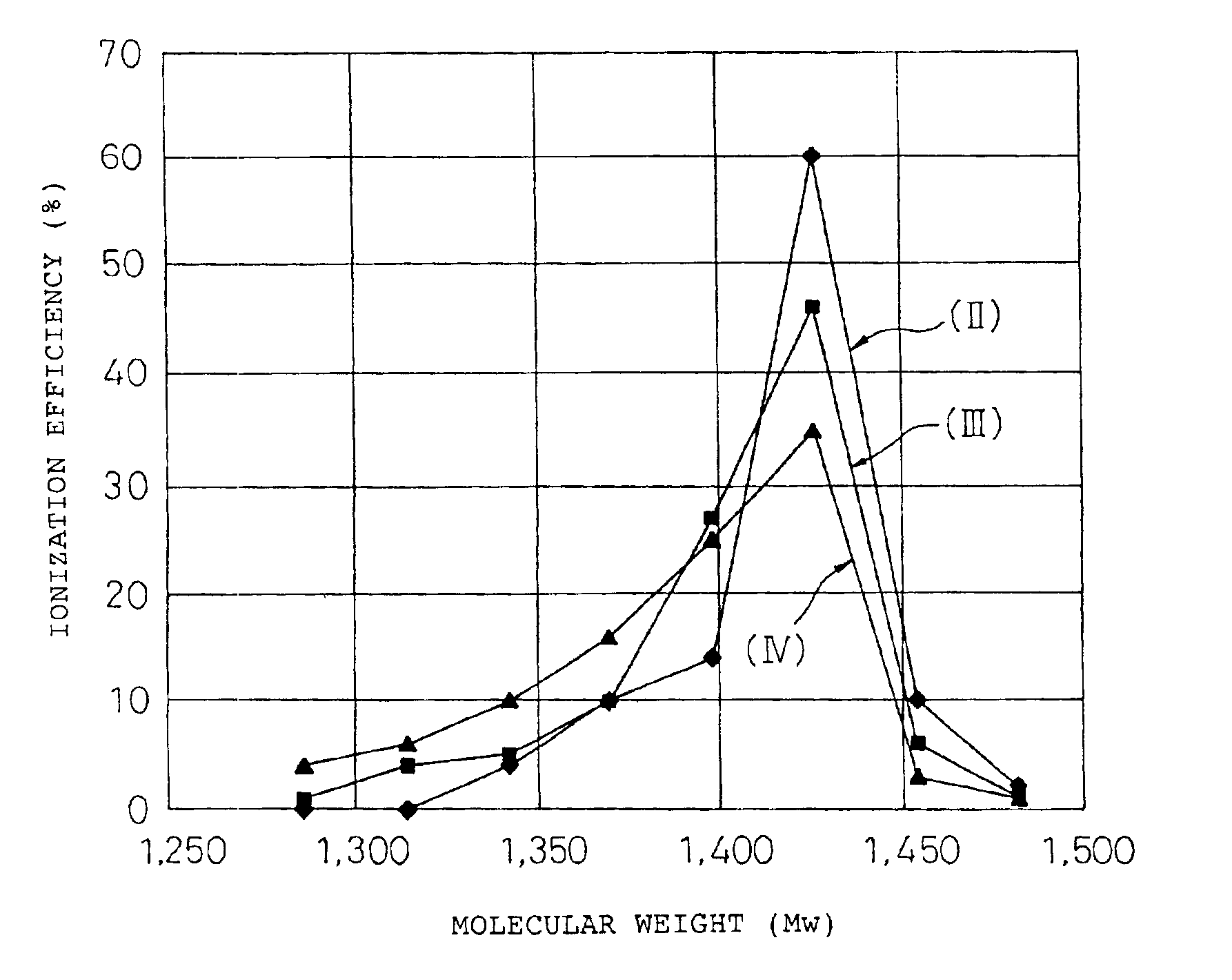
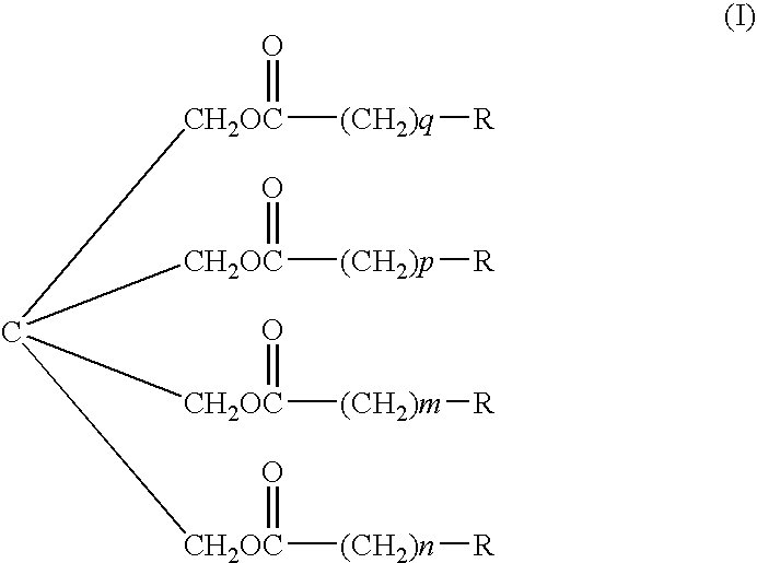
Polyester resin containing 5% by weight of chloroform-84 partsinsoluble content (propylene oxide adduct of bisphenol A,prepared by using terephthalic acid and trimellitic acid asa raw material component, grass transition temperature: 62to 66° C., acid value: about 20 mg KOH / g, manufacturedby Kao Corp.)Polypropylene resin (weight-average molecular weight: 2 parts10,000, 2 parts, manufactured by Mitsui Chemicals under thetrade name of “NP105”)Ester type resin (II) (see the following formula, 3 partsmanufactured by Nippon Oil & Fats Co., Ltd.)ColorantCarbon (#25, manufactured by10 partsMitsubishi Chemical)Charge controllingSulfonic acid polymer (manufactured 1 partagentby Hodogaya Chemical CO., Ltd.under the trade name of “T-95”)

[0123]These toner components were preliminary mixed by charging in a ball mill and then the mixture was melted and knead...

example 2

Preparation of Toners 2 to 31:

[0124]The same method as in Example 1 was repeated to prepare toners in the form of fine spherical particles. In these examples, as described in Tables 2 and 3 described hereinafter, combinations and amounts of toner components were changed. Change points of the respective toners are summarized as follows.

[0125]

“Toner 2“Chloroform-insoluble content in polyester resin10%by weight“Toner 3”Chloroform-insoluble content in polyester resin20%by weight“Toner 4”Chloroform-insoluble content in polyester resin30%by weight“Toner 5”Chloroform-insoluble content in polyester resin3%by weight“Toner 6”Polyester resin85.5partsChloroform-insoluble content in polyester resin2%by weightPolypropylene resin0.5parts“Toner 7”Polyester resin85.5partsPolypropylene resin0.5parts“Toner 8”Polyester resin85.99partsPolypropylene resin0.01parts“Toner 9”Polyester resin81partsPolypropylene resin5parts“Toner 10”Polyester resin79partsPolypropylene resin7parts“Toner 11”Polyester resin86par...

example 3

Preparation of Carrier 1:

[0126]Manganese-strontium (Mn—Sr) ferrite particles (Powdertech Co.) having an average particle diameter of 80 μm as a carrier core material were prepared and then the surface of this core material was coated with a silicone resin (solid content: 20% by weight, manufactured by TORAY DOW CORNING SILICONE CO., LTD. under the trade name of “SR2411”) containing a mixture of a nigrosine complex and sodium stearate (manufactured by Orient Chemical Industries Co., Ltd. under the trade name of “N-11”) in a coating weight of 0.1% by weight using a fluidized bed. After the completion of coating, the coated core material was baked at a temperature of 250° C. for three hours. As a result, a Mn—Sr ferrite carrier coated with a silicone resin was obtained. The resulting carrier is referred to as “carrier 1”, hereinafter.


PUM

PropertyMeasurementUnit
molecular weight distributionaaaaaaaaaa
temperatureaaaaaaaaaa

Abstract

An electrophotographic toner comprising a binder resin and a colorant, which is used in electrophotographic process employing a flash fixing system for fixation of a transferred toner image, wherein
    • the binder resin is a polyester resin which partially contains a chloroform-insoluble content; and
    • the toner contains a polypropylene resin and an ester type structure resin represented by the following formula (I);
    • wherein p, q, m and n each represents a positive integer of 16 to 22 and R may be the same or different and each represents a hydrogen atom or a lower alkyl group having 1 to 4 carbon atoms. The electrophotographic toner is capable of remarkably enhancing the fixation strength of the toner and inhibiting the occurrence of voids during the printing and the occurrence of fuming and odor during the fixation.

Description

CROSS-REFERENCE TO RELATED APPLICATIONS[0001]This application is a continuation of PCT / JP00 / 01678, filed Mar. 17, 2000, which is based upon and claims the priority of PCT / JP99 / 03822, filed Jul. 15, 1999, the contents being incorporated herein by reference.TECHNICAL FIELD[0002]The present invention relates to an electrophotographic toner and, more particularly, to an electrophotographic toner, suitable for use in a flash fixing system, which can be used advantageously as a developing agent in various imaging apparatuses employing the electrophotographic system such as, for example, an electrophotographic copying machine, an electrophotographic printer and an electrostatic printing machine. The present invention also relates to an image forming method which employs the electrophotographic toner.BACKGROUND ART[0003]As is well known, the operation of an electrophotographic system, which has been widely used in copying machines, printers and printing machines, generally includes the foll...

Claims


Application Information

Patent Timeline
Patent Type & Authority Patents(United States)
IPC IPC(8): G03G13/00G03G13/20G03G9/087G03G9/097
CPCG03G9/08704G03G9/08742G03G9/08755G03G9/08782G03G9/09733G03G13/20
Inventor NAKAMURA, YASUSHIGETAKAHASHI, TORUWATANUKI, TSUNEOSAWATARI, NORIOISHIMARU, SEIJIROFURUSE, YASUYUKI
Owner FUJIFILM BUSINESS INNOVATION CORP
Why Eureka
Try Eureka