Phase-locked loop filter with out of band rejection in low bandwidth mode

a phase-locked loop filter and low bandwidth technology, applied in the field of wideband modulation, can solve the problems of limiting the output signal accuracy, and affecting the accuracy of output signals

Inactive Publication Date: 2005-11-22
MEDIATEK INC
View PDF9 Cites 52 Cited by
  • Summary
  • Abstract
  • Description
  • Claims
  • Application Information

AI Technical Summary

Problems solved by technology

A typical drawback of a voltage-controlled oscillator is its uncertainty in output frequency to the applied input voltage due to integrated circuit process variations.
This phase noise at the voltage-controlled oscillator output is undesirable as this limits the accuracy of the output signal.
For signal reception, impure frequency sources result in mixing of undesired channels into the desired channel signal.
For signal transmission, impure frequency sources create interference in neighboring channels.
The level of spectral purity required in cellular telephone applications makes the design of a phase-locked loop synthesizer solution and, in particular, the design of a voltage-controlled oscillator within a phase-locked loop synthesizer solution quite demanding.
Phase noise is undesired energy spread continuously in the vicinity of the output frequency, invariably possessing a higher power density at frequencies closer to the fundamental of the output frequency.
Phase noise is often the most damaging of the three to the spectral purity of the output frequency.
It is often the case that the series resistance of the inductor is the dominant loss mechanism in an LC tank oscillator, although other losses typically exist.
Decreasing the charge pump current increases the relative noise of the charge pump and decreases the phase-locked loop slew rate.
Another barrier to integration is the lack of precision in the values of the inductors and capacitors used in the LC tank of the phase-locked loop.
This tolerance problem typically forces most phase-locked loop synthesizer implementations to modify the inductor or capacitor values during production, for example, by laser trimming.
Further complicating integration is the difficulty in integrating an inductor with a low series resistance and a capacitor with a reasonably high value and with low loss and low parasitic characteristics.
In integrating capacitance values, a significant problem is the high value of a typical loop filter capacitor component, which is often on the order of 500 pf to 5000 pf.
Another significant problem is the absence of a variable capacitance component that possesses a highly-variable voltage-controlled capacitance that is not also a high loss component that causes phase noise.
However, such high-performance varactors require special processing and, therefore, have not been subject to integration with the rest of the phase-locked loop circuitry.
In short, although integration onto a single integrated circuit of a phase-locked loop implementation for synthesizing high-frequency signals is desirable for a commercial cellular phone application, integration has yet to be satisfactorily achieved.

Method used


Image

  • Phase-locked loop filter with out of band rejection in low bandwidth mode
  • Phase-locked loop filter with out of band rejection in low bandwidth mode
  • Phase-locked loop filter with out of band rejection in low bandwidth mode

Examples


Embodiment Construction

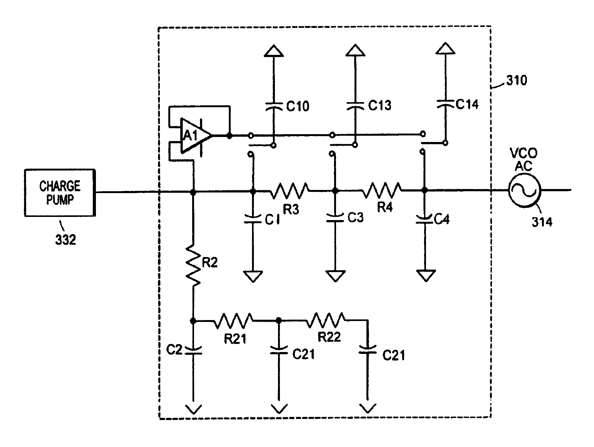
[0049]As noted above, the present invention contemplates a method and apparatus for synthesizing high-frequency signals by implementing a phase-locked loop frequency synthesizer with a voltage controlled oscillator. FIG. 3 illustrates an example of an apparatus for synthesizing high-frequency signals by implementing a phase-locked loop frequency synthesizer with a voltage controlled oscillator according to the concepts of the present invention.

[0050]As shown in FIG. 3, a sigma-delta modulator and digital to analog converter circuit 300 receives a Gaussian frequency shifted key signal. The sigma-delta modulator and digital to analog converter circuit 300 modulates and converts the signal to an analog signal. Upon leaving the sigma-delta modulator and digital to analog converter circuit 300, the analog signal is filtered by lowpass filter 302. The filtered signal is scaled by programmable gain amplifier 304 and then attenuated by modulation attenuation circuit 306 before being fed int...


PUM


Abstract

A wideband impedance attenuator includes a phase-locked loop filter, a voltage-controlled oscillator connected to the phase-locked loop filter during transmit, and an impedance circuit connected to the phase-locked loop filter and the voltage controlled oscillator. The impedance circuit is a scaled version of the phase-locked loop filter. Moreover, the wideband impedance attenuator attenuates a Gaussian frequency shift key modulation signal by a factor of 1 / (N+1) using the impedance circuit, which has an impedance of N*Z(s), and the phase-locked loop filter, which has an impedance of Z(s). An output frequency is generated using a voltage-controlled oscillator wherein the output frequency corresponds to the attenuated Gaussian frequency shift key modulation signal. In addition, a comparator compares a voltage of an output from the programmable gain amplifier with a voltage necessary to produce a predetermined frequency shift in a voltage-controlled oscillator to produce a gain signal. A gain controller, in response to the gain signal produced by the comparator, controls a gain of the programmable gain amplifier.

Description

CROSS-REFERENCE TO RELATED US PATENT APPLICATIONS[0001]This application is a divisional of U.S. patent application Ser. No. 10 / 230,697, now U.S. Pat. No. 6,844,763, filed on Aug. 29, 2002. The entire contents of U.S. patent application Ser. No. 10 / 230,697 are hereby incorporated by reference.FIELD OF THE PRESENT INVENTION[0002]The present invention is directed to wideband modulation in a communication device using a phase-locked loop and voltage-controlled oscillator. More particularly, the present invention is directed to a wideband modulation summing network that scales a voltage signal being fed to a voltage-controlled oscillator and a calibration gain circuit that controls the scaling of the modulated signal.BACKGROUND OF THE PRESENT INVENTION[0003]Phase-locked loops are used in a variety of applications such as clock recovery, frequency and phase modulation, and frequency synthesizers. A voltage-controlled oscillator is a central design element of the phase-locked loop, whereby...

Claims


Application Information

Patent Timeline
Patent Type & Authority Patents(United States)
IPC IPC(8): H03L7/06H03C3/09
CPCH03C3/0925H03C3/0941H03C3/095H03C3/0991
Inventor BALBONI, EDMUND J.
Owner MEDIATEK INC
Why Eureka
Try Eureka