

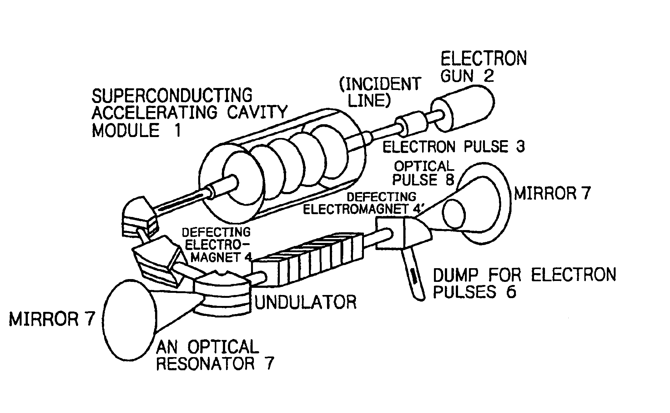
Method and a device for realizing both high extraction efficiency of laser light from electron beams and femto-second ultra-short in free-electron lasers pulses
a free-electron laser and laser light technology, applied in the field of free-electron lasers, can solve the problems of sacrificing energy tunability, reducing the intrinsic small gain of free-electron lasers, and unable to stably realize required experimental conditions, etc., to achieve high laser gain, increase the extraction efficiency of laser light, and high average power
- Summary
- Abstract
- Description
- Claims
- Application Information
AI Technical Summary
Benefits of technology
Problems solved by technology
Method used
Image

Examples
example 1
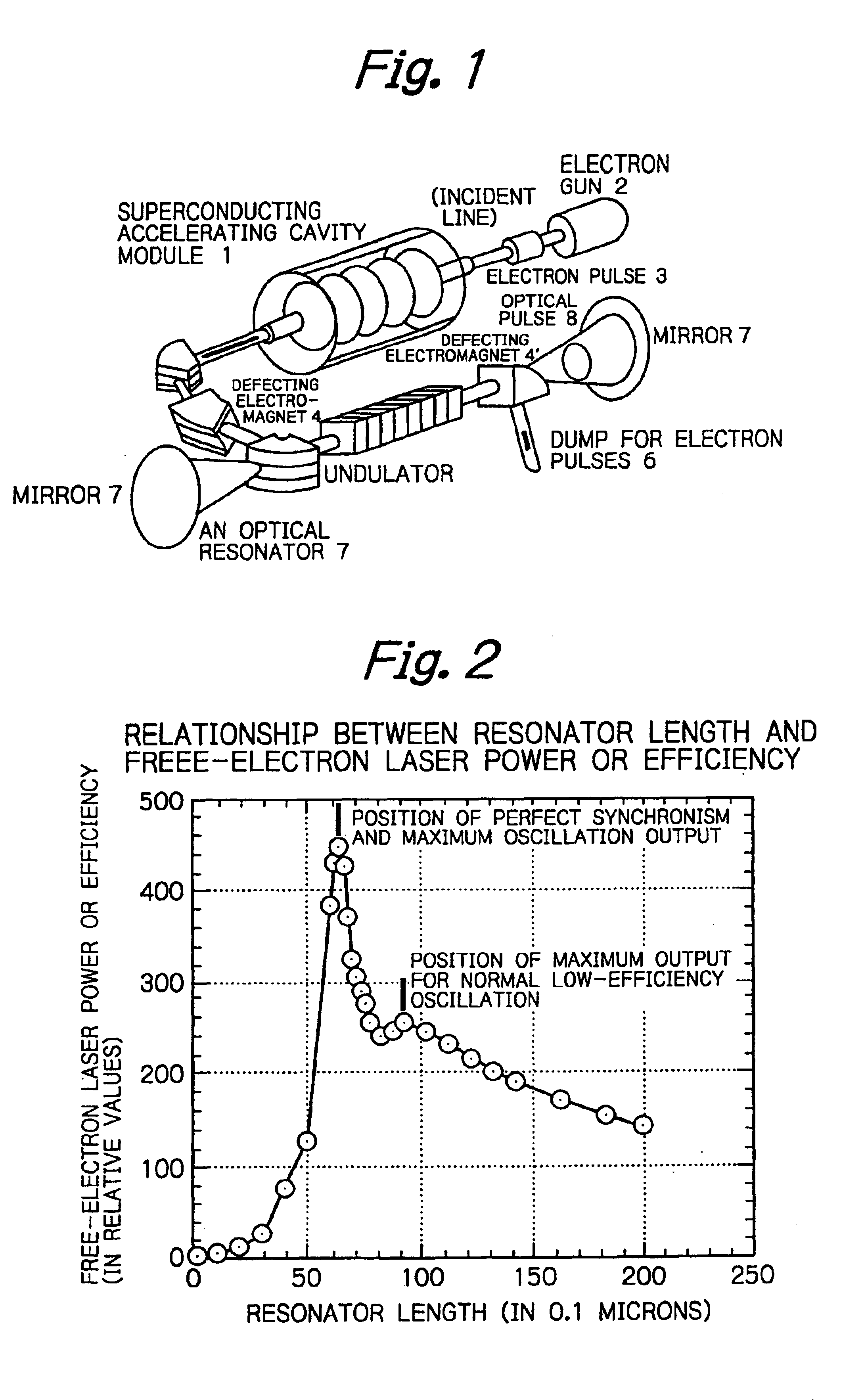
[0026]The normal conducting or superconducting linear accelerator as the driver is designed to operate in continuous wave having an adequately high peak current and an adequately long duration of electron pulse. As shown in FIG. 2, if the length of the resonator is increased from the position where it is well shorter than the length associated with the repetition of electron pulses toward the point of agreement, two peaks appear and laser oscillation of maximum intensity stops abruptly if the resonator becomes slightly longer than when it is at the position of perfect agreement.
[0027]The second and smaller peak or the second maximum point providing a shoulder represents the state of pulses having the longer time duration that are produced by normal oscillation of low-efficiency and low-output. This peak is found at the position where the resonator length is shortened by about 10% of the wavelength of laser in order to compensate for the difference in velocity between light and elect...
example 2
[0029]The normal conducting or superconducting linear accelerator as the driver is designed to operate on continuous waves having an adequately high peak current and an adequately long pulse duration. Referring again to FIG. 2 which shows a curve representing the correlation between resonator length and power (detuning curve), the laser wavelength resolution width, efficiency and output power vary with respective parts of the curve. Using this feature, diagnosis and measurements of various factors such as the wavelength dependency of the rate of reaction and so on are performed by operating the free-electron laser at low power, low efficiency and higher-resolution. Other operations such as treatment and decomposition are performed by operating the free-electron laser in the state of perfect synchronism characterized by high power, high efficiency and lower-resolution.
example 3
[0030]If the superconducting linear accelerator as the driver is used to lase at low efficiency (<1%), energy recovery geometry and operation can be accomplished. Irrespective of whether the linear accelerator is normal conducting or superconducting, only low percentage of energy recovery becomes possible if the efficiency is approximately from several to ten percent; however, laser light of high power can be obtained, and the generation of radiation can be produced, particularly the production of radioactivity inducing neutrons down to several orders of magnitude.
PUM
 Abstract
Description
Claims
Application Information