Delay compensation for stable current regulation when using variable-delay random PWM switching

a random pwm switching and delay compensation technology, applied in the direction of motor/generator/converter stopper, dynamo-electric converter control, dynamo-electric gear control, etc., can solve the problem that the maximum code size is limited by the minimum sample period, the length of the code may not allow a sufficiently high switching frequency to achieve good spectral spreading

Active Publication Date: 2005-12-06
GM GLOBAL TECH OPERATIONS LLC
View PDF8 Cites 67 Cited by
  • Summary
  • Abstract
  • Description
  • Claims
  • Application Information

AI Technical Summary

Benefits of technology

[0009]According to the principles of the present invention, a control system for an electric machine is provided having an advantageous construction. The control system includes a rotor position sensor that generates a rotor position signal, a velocity module that generates an electric angular velocity value based on the rotor position signal, a random pulse width modulation module that generates a switching period and a delay for a current cycle, and a phase angle compensation module that sums a sample rate, one half of the switching period, and the delay of a previous cycle and that outputs a delay time. The phase angle compensation module further multiplies the delay time and the electric angular velocity value and generates a compensating angle.

Problems solved by technology

However, these RSF systems suffer from a significant disadvantage, namely the maximum code size is limited by the minimum sample period.
For complicated motor control algorithms, the length of code may not allow sufficiently high switching frequency to achieve good spectral spreading.
For example, random zero vector, random center displacement, and random lead-lag techniques all maintain synchronous sample and PWM period, but suffer some form of limitation.
For example, random zero vector and random center displacement lose effectiveness at high modulation indexes.
Random lead-lag does not offer suitable performance with respect to reducing acoustic / EMI emissions and, further, suffers an increased current ripple.
Additionally, both random lead-lag and random center displacement introduce an error in the fundamental component of current due to a per-cycle average value of the switching ripple.
However, conventional VD-RPWM suffers from disadvantages when operated at high fundamental frequencies.
In these cases, the delay introduced by VD-RPWM may cause undesirable instability.

Method used


Image

  • Delay compensation for stable current regulation when using variable-delay random PWM switching
  • Delay compensation for stable current regulation when using variable-delay random PWM switching
  • Delay compensation for stable current regulation when using variable-delay random PWM switching

Examples


Embodiment Construction

[0018]The following description of the preferred embodiment is merely exemplary in nature and is in no way intended to limit the invention, its application, or uses. As used herein, the term “module” refers to an application specific integrated circuit (ASIC), an electronic circuit, a processor (shared, dedicated, or group) and memory that execute one or more software or firmware programs, a combinational logic circuit, and / or other suitable components that provide the described functionality.

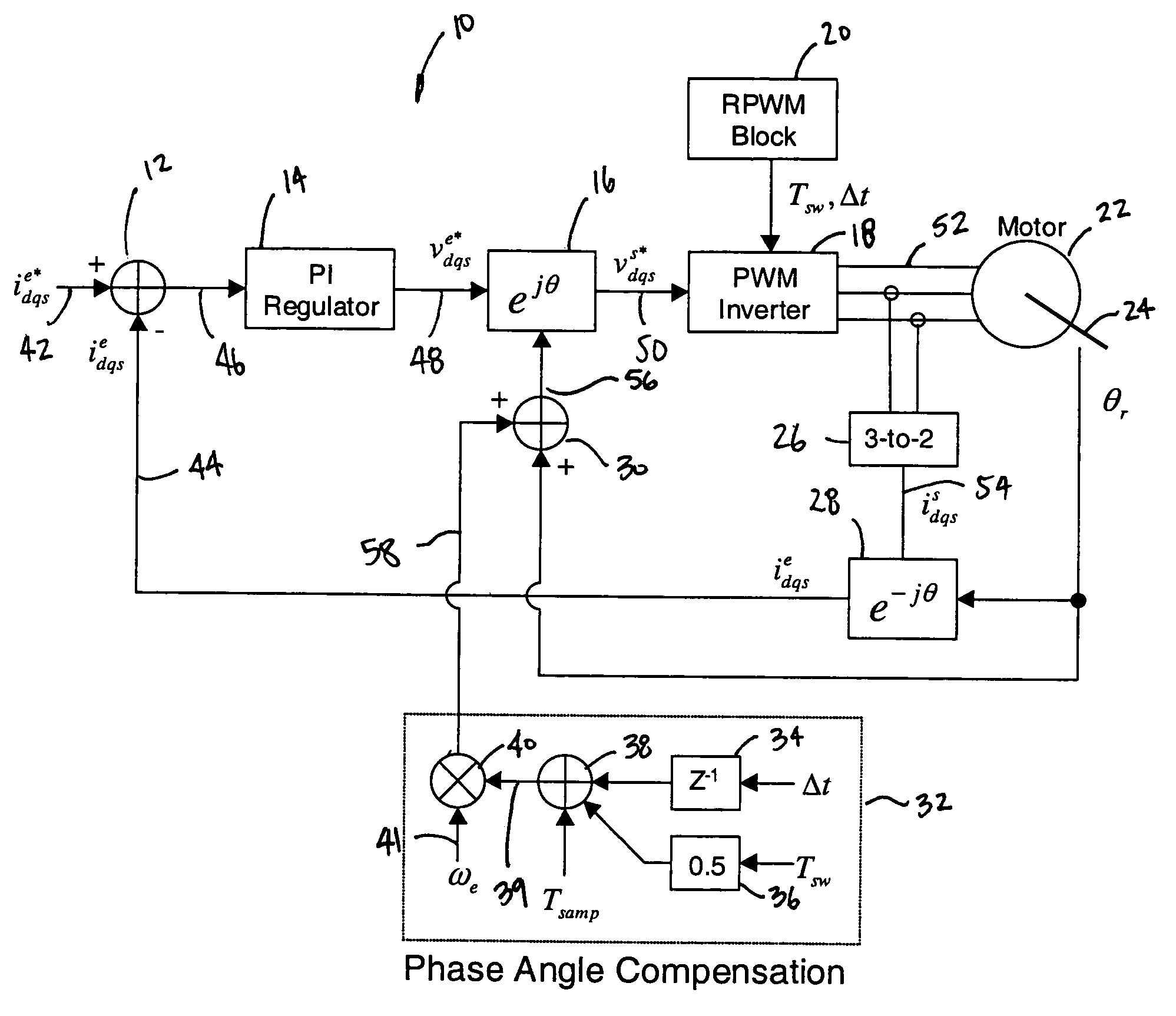
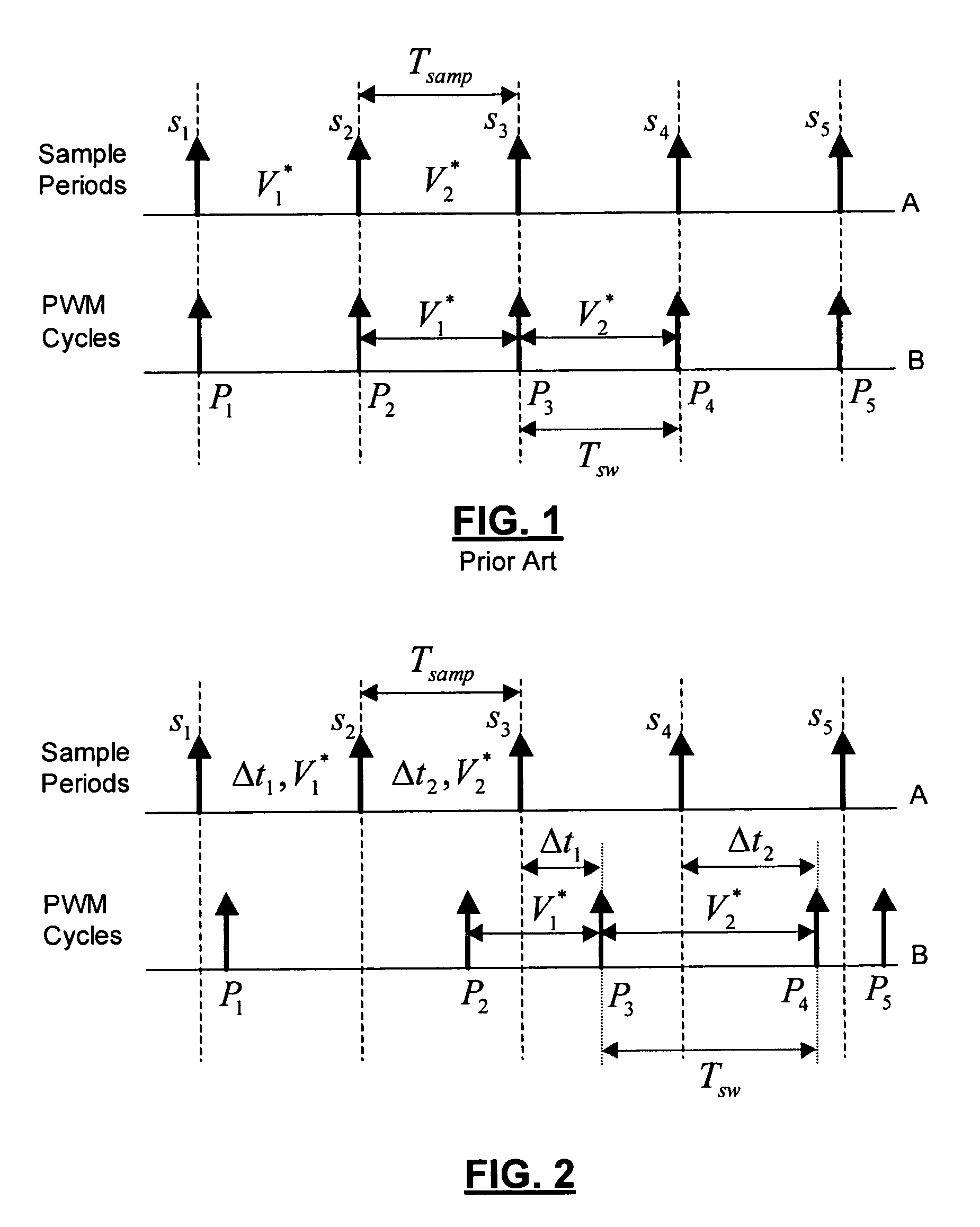
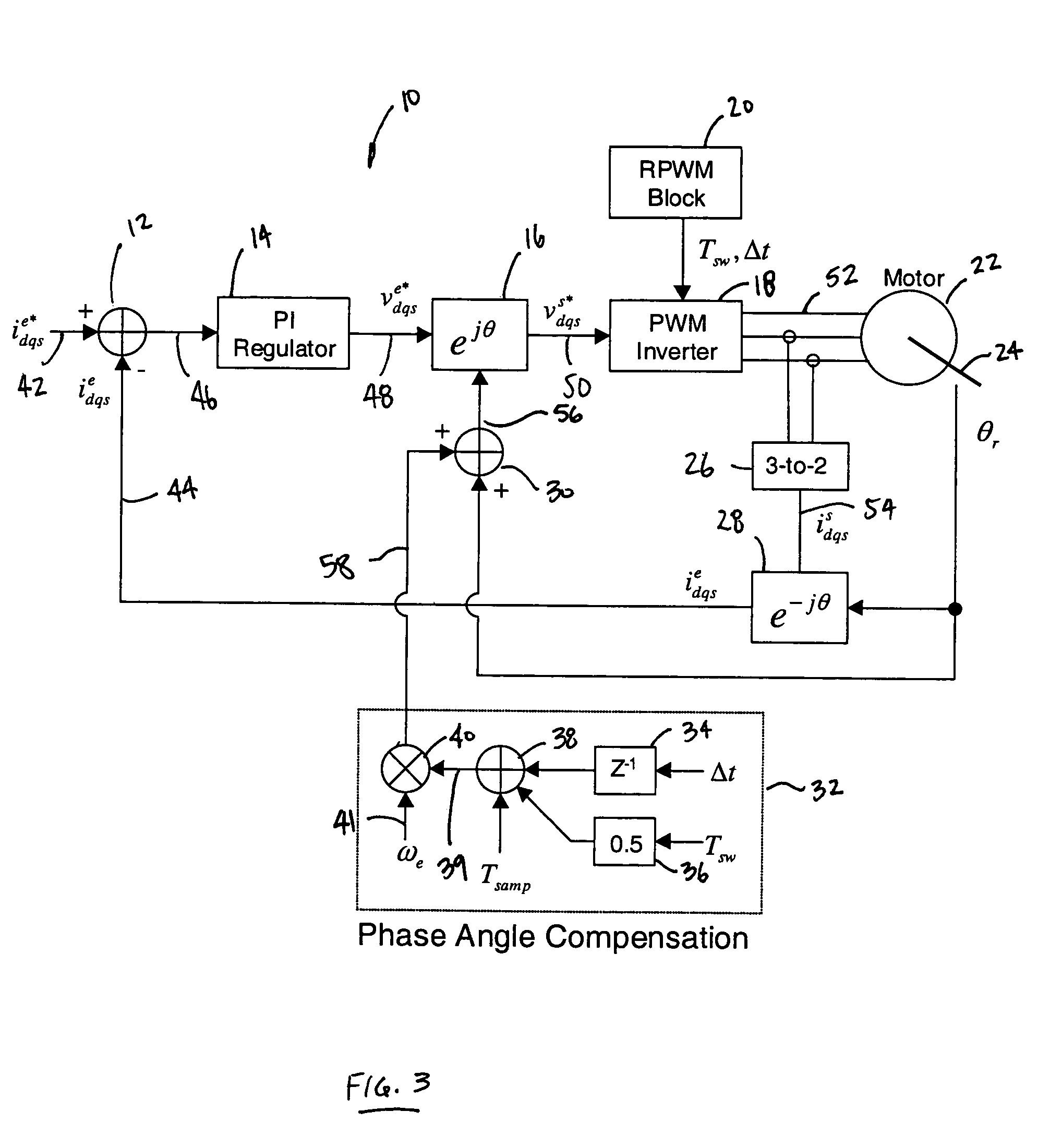
[0019]As discussed above, conventional variable-delay random pulse width modulation (VD-RPWM) provides a number of significant advantages over other RPWM techniques. According to conventional VD-RPWM, the sample rate (input), Tsamp, remains constant while the PWM output period, Tsw, is randomly varied from Tsw—min to 2*Tsamp, where Tsw—min is the minimum PWM switching period to be allowed and Tsamp is the sample rate. This wide range in PWM output period provides excellent spectral spreading in...


PUM


Abstract

A control system for an electric machine having a rotor position sensor that generates a rotor position signal, a velocity module that generates an electric angular velocity value based on the rotor position signal, a random pulse width modulation module that generates a switching period and a delay for a current cycle, and a phase angle compensation module that sums a sample rate, one half of the switching period, and the delay of a previous cycle and that outputs a delay time. The phase angle compensation module further multiplies the delay time and the electric angular velocity value and generates a compensating angle.

Description

FIELD OF THE INVENTION[0001]The present invention relates to power converters and, more particularly, relates to a current regulation system used to compensate for the delay introduced by variable-delay random pulse width modulation.BACKGROUND OF THE INVENTION[0002]Random pulse width modulation (RPWM) is recognized as a desirable technique to reduce both electromagnetic and acoustic noise emissions from pulse width modulation (PWM) inverters. RPWM is generally characterized by random variations of the switching frequency. The random variations of the frequency alleviate undesirable characteristics in PWM electronic power converters. Specifically, the fundamental AC component harmonics remain unchanged. However, the spectral power, measured in Watts, is converted to continuous power density, measured in Watts per Hertz, instead of being concentrated in discrete harmonics. The power spectra of the output voltage and current from a RPWM power converter emulate the spectrum of white noi...

Claims


Application Information

Patent Timeline
Patent Type & Authority Patents(United States)
IPC IPC(8): H02K23/00H02P21/00
CPCH02P21/0035H02P21/22
Inventor SCHULZ, STEVEN E.KOWALEWSKI, DANIEL L.
Owner GM GLOBAL TECH OPERATIONS LLC
Why Eureka
Try Eureka