Electromagnetic active vibration control system and electromagnetic actuator

a technology of electromagnetic actuators and active vibration control, which is applied in the field of electromagnetic systems, can solve the problems of nonlinear behavior and harmonic distortion, difficult and expensive installation and maintenance, and achieve the effects of accurate, robust and efficient, easy installation and maintenance, and low cos

Inactive Publication Date: 2005-12-13
VSSL COMML
View PDF13 Cites 10 Cited by
  • Summary
  • Abstract
  • Description
  • Claims
  • Application Information

AI Technical Summary

Benefits of technology

[0008]An important aspect of the present invention involves the improved construction of the actuator. In a preferred embodiment of the invention, each actuator is characterized by an armature on one side of a gap and a magnet coil on the other side of the gap. A magnetic force is generated across the gap, and that force is linearized by flux feedback. The relatively uncomplicated actuator of the present invention is more accurate, robust, and efficient (especially at low frequencies) than prior art inertial shakers.
[0010]Several features distinguish the actuator of the present invention from other devices that have been suggested for active vibration control. The known systems generally use reaction-mass shakers, pneumatic or hydraulic actuators. Such technologies have moving parts such as bearings, seals and springs that require periodic overhaul. An electromagnet has no moving parts, can easily be made impervious to fluids and dust, and can operate for many years with little or no maintenance. Moreover, electromagnets may be less expensive than other devices. In addition, shakers and other known devices are generally large and bulky so as to achieve useful force levels at low frequencies (generally less than 20 Hertz). The known devices may be prone to nonlinear behavior and harmonic distortion. By contrast, an electromagnet constructed in accordance with the present invention, with appropriate real time control, can generate the necessary forces with a compact and simple actuator that can easily be retrofitted into preexisting machinery spaces. The actuators may be deployed in clusters or distributed groups to generate larger forces if necessary.
[0021]In a preferred embodiment of the present invention, it is not necessary to generate a probe signal during the control-on regime (i.e., during the active mode).

Problems solved by technology

The Rossetti et al. system employs shaker-type electromagnetic elements, which can be difficult and expensive to install and maintain, and which are prone to nonlinear behavior and harmonic distortion.

Method used


Image

  • Electromagnetic active vibration control system and electromagnetic actuator
  • Electromagnetic active vibration control system and electromagnetic actuator
  • Electromagnetic active vibration control system and electromagnetic actuator

Examples


Embodiment Construction

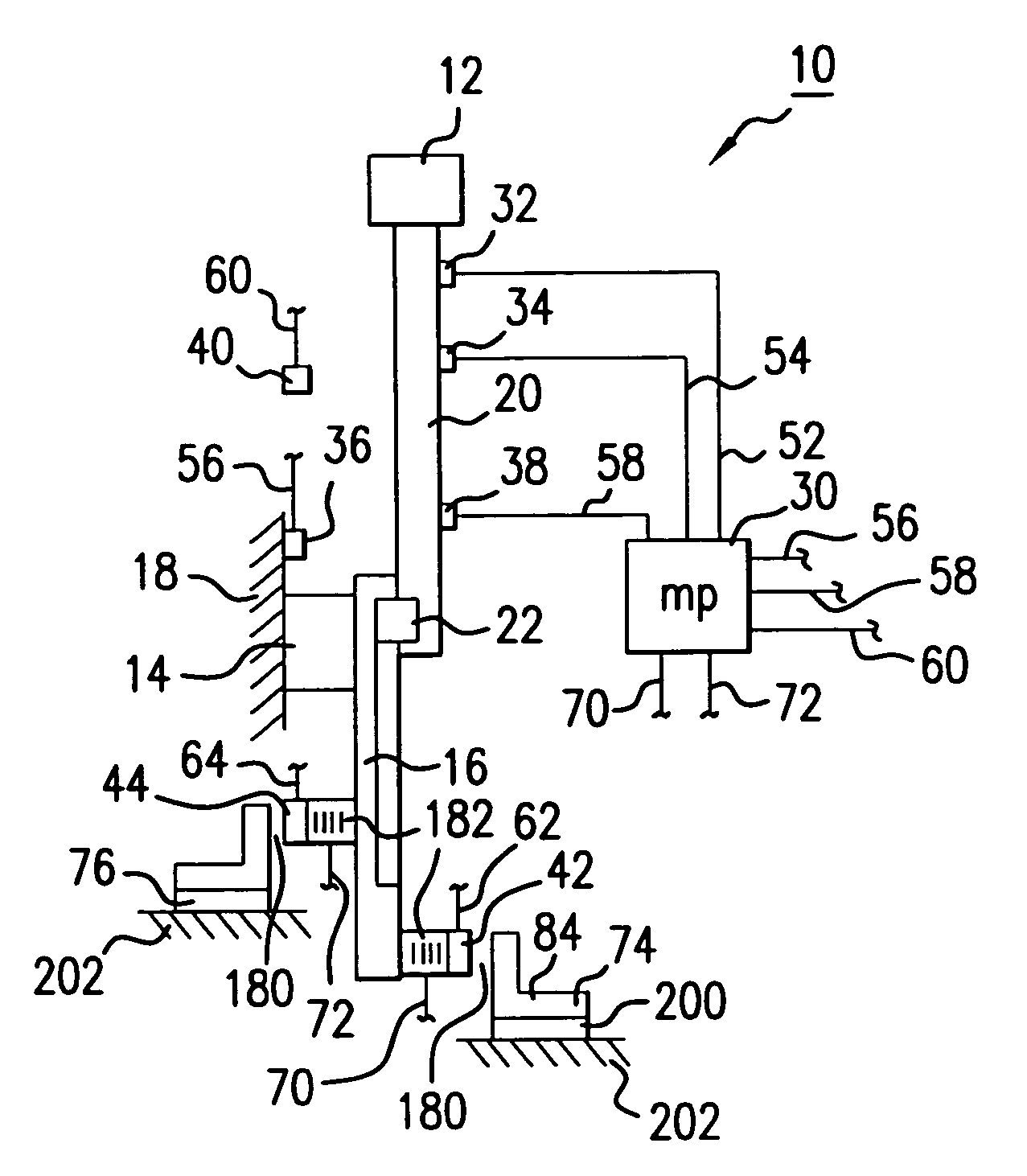
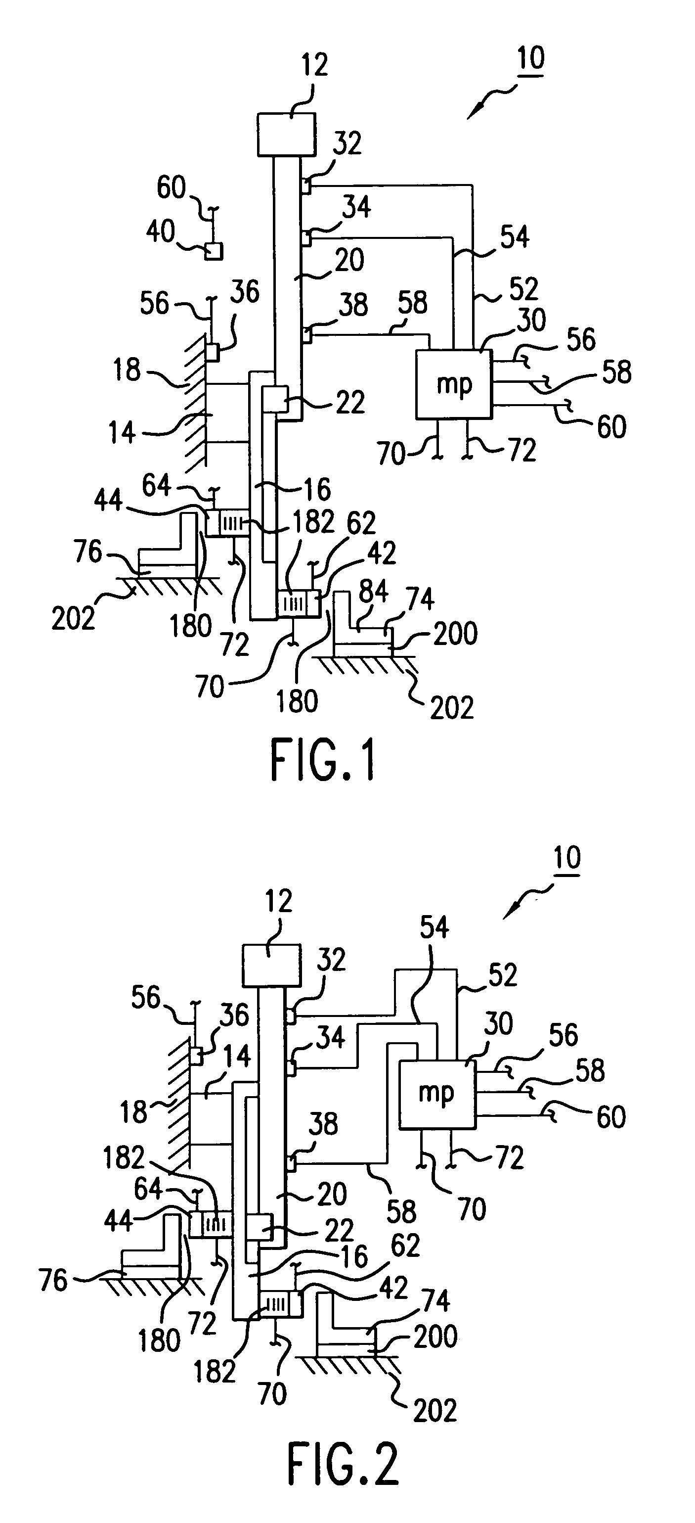
[0027]Referring now to the drawings, where like reference numerals designate like elements, there is shown in FIG. 1 an industrial apparatus 10 for supporting a work product 12. The work product 12 may be, for example, payload materials that are being processed by the apparatus 10. The industrial apparatus 10 has a support mechanism 14, 16 that is integrally fixed to a rigid exterior body 18. A slender, extendable beam 20 is connected to and movably supported by the support mechanism 16. A suitable mechanism 22, located on or in the support mechanism 16, causes the beam 20 to move to and fro, such that the work product 12 moves back and forth between first and second positions. The second position for the supported work product 12 is shown in FIG. 2.

[0028]In an inactive mode, external rotating machinery (not shown) generates low frequency incident vibration in the exterior body 18. The vibration is transmitted through the support structure 14, 16 and through the extendable beam 20 t...


PUM


Abstract

A multi-sensor, multi-actuator control system for controlling vibration in a mechanical structure. The system employs feedforward and feedback control strategies in tandem. Outputs from adaptive feedforward and modal feedback control loops are added to each other. The control system may be dynamically adapted to the changing physical characteristics of the controlled structure. For example, the plant transfer function estimates for the feedforward unit and the gain for the feedback unit may be calculated as functions of sensed physical parameters (location, mass, etc.), and the plant transfer function estimates may be dynamically modified to reflect time-varying feedback control gains. If desired, the control system may be used to cancel low frequency vibrations (<20 Hz) in industrial processes. The actuators may be formed of electromagnets, fixed armatures and interposed flux sensors. In a preferred embodiment of the invention, the robust actuators are sealed so as to be impervious to fluids and dust.

Description

BACKGROUND OF THE INVENTION[0001]1. Field of the Invention[0002]The present invention relates to electromagnetic systems for reducing, eliminating and / or monitoring vibration in variable-state mechanical and / or industrial structures. The invention also relates to an electromagnetic actuator for use in connection with industrial equipment and other apparatuses. The invention also relates to a vibration control system that is dynamically responsive to changing physical and / or environmental characteristics (position, mass, rate of throughput, etc.) of the controlled structure.[0003]2. Discussion of the Related Art[0004]U.S. Pat. No. 5,796,849 (Coleman et al.) refers to a system for actively controlling noise and structural vibration. The Coleman et al. patent relates to situations where the dynamics of the transfer functions between the actuator devices and the residual sensors change over time. In the Coleman et al. system, a probe signal is used to obtain a current estimate of the pl...

Claims


Application Information

Patent Timeline
Patent Type & Authority Patents(United States)
IPC IPC(8): F16F15/02B06B1/04F16F7/10F16F15/00F16F15/03G05D19/02
CPCF16F15/002F16F15/03G05D19/02
Inventor RUCKMAN, CHRISTOPHER E.HOLFORD, JOHN M.
Owner VSSL COMML
Why Eureka
Try Eureka