
Water treatment process for thermal heavy oil recovery

a technology of thermal heavy oil and water treatment process, which is applied in the direction of refrigeration components, refrigeration machines, borehole/well accessories, etc., can solve the problems of increased temperature of the recovered production fluid (oil and water), increased difficulty in recovering, and increased risk of steam generator operation, so as to facilitate water recovery and reduce input costs

Inactive Publication Date: 2006-01-10
FOUNTAIN QUAIL WATER MANAGEMENT LLC +1
View PDF138 Cites 56 Cited by
  • Summary
  • Abstract
  • Description
  • Claims
  • Application Information

AI Technical Summary

Benefits of technology

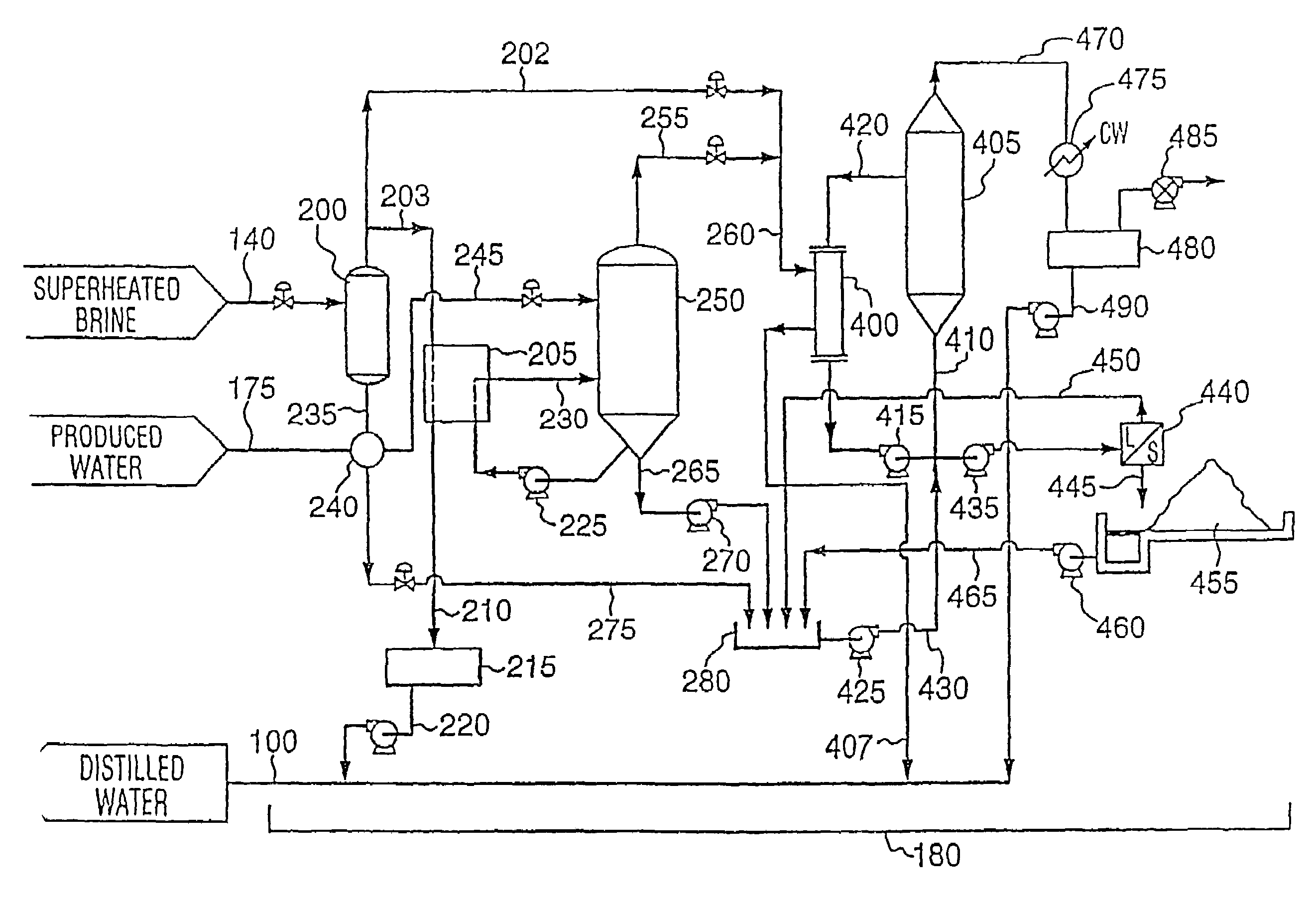
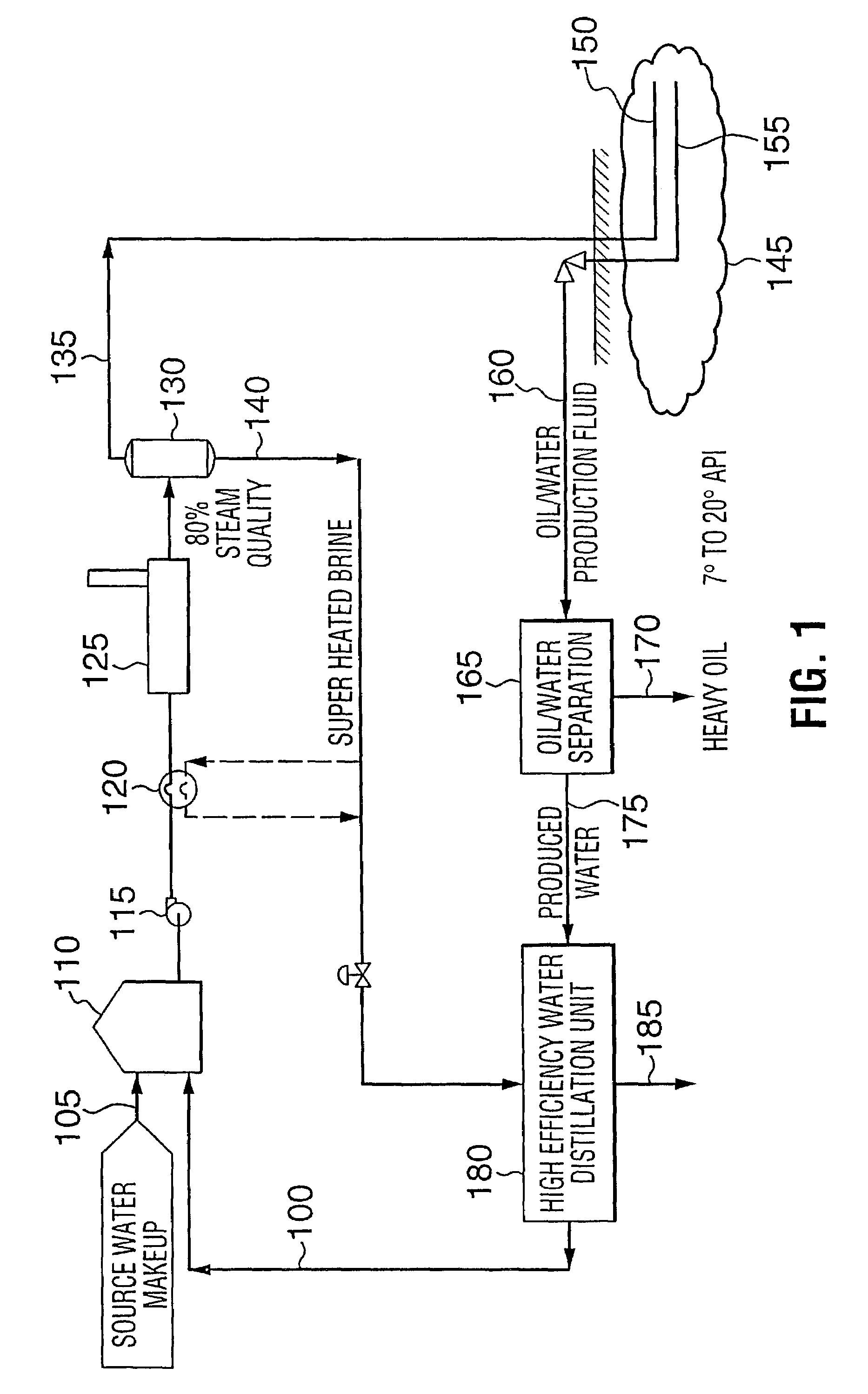
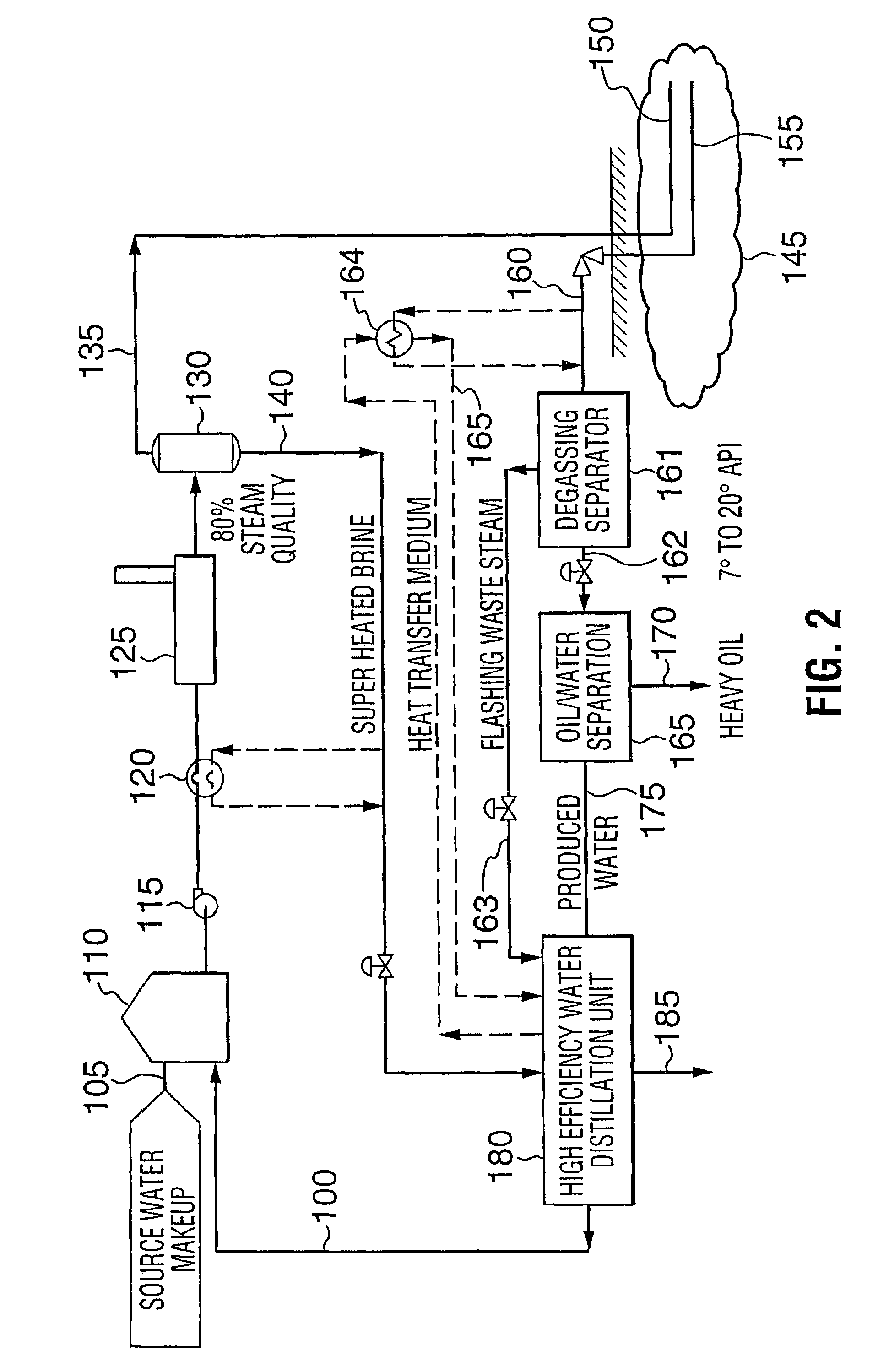
The present invention provides a method for recovering energy from water produced during heavy oil recovery. The method involves using a high pressure blowdown stream, flashing the stream to form a low pressure waste energy stream and a concentrated blowdown stream, preheating the produced water with the concentrated blowdown stream, and circulating the water through a heated separator and a reboiler exchanger to maintain a ratio of mass of concentrate to vapor fraction of 300 to near 2. The method also includes providing a vapor circuit and a crystallization means to precipitate solids from the concentrate liquid contaminant fraction. The method reduces input costs and results in a zero waste water effluent solution.

Problems solved by technology

Throughout the many regions in the world, heavy oil, a hydrocarbon material having much higher viscosity or lower API gravity (less than 20° API, typically 7° to 12° API) than conventional petroleum crude, is more difficult to recover and requires enhanced thermal stimulation techniques of the subsurface reservoir to produce.
If this brackish water is recycled without treatment, the operation of the steam generators is at risk due to fouling and scaling.
A further problem encountered with the current heavy oil recovery practices using steam injection, is that as the operating temperatures of producing reservoirs are increased from 230° F. to greater than 400° F. to enhance the heavy oil recovery, the temperature of the recovered production fluids (oil and water) increase.
The heat energy of the condensing steam is discharged to the atmosphere and wasted.
However, water distillation processes typically have several problems not the least of which can be fouling or scaling of the apparatus with minerals or other components from the fluid being distilled.
Fouling, or to a greater extent, scaling of the heat transfer surfaces have a detrimental effect on the capacity of the heat transfer components, causing conventional distillation processes to become inoperable.
Moreover, Tsurata teaches a way from recovering waste heat as he indicates it disadvantageous to use 2 heat exchangers as there is an increase in energy consumption.
Another common problem with typical water distillation processes is high energy input requirements.
Water distillation, under this condition is not commercially viable for water remediation applications.

Method used


Image

  • Water treatment process for thermal heavy oil recovery
  • Water treatment process for thermal heavy oil recovery
  • Water treatment process for thermal heavy oil recovery

Examples


example 1

[0126]This example calculation is a means of demonstrating the heat balance around the reboiler exchanger. This example represents a design basis of a distillation unit designed to recover 53,000 USGPD of clean distillate from a contaminated source.

[0127]

Exchanger InformationSurface Area3,200 ft2TypeGasketed Plate-FrameU542 BTU hr−1 ft−2 F−1Corrected LMTD10.40 FCalculated Service Duty(3,200)*(542)*(10.40)18,041,224 BTU hr−1Calculated Heat Flux(18,041,224) / (3200)5638 BTU hr−1 ft−2Condensing SideInlet Conditions289° F. @ 21.0 psia (superheated)Outlet Conditions231.8° F. @ 20.9 psiaSaturated Condensing232.0° F. @ 21.0 psiaTemperatureLatent Heat of Condensing957.4 BTU lb−1 @ 21.0 psiaSteam Flow36.7 USgpm = 18,352 lb hr−1QDESUPERHEAT(18,352)*(0.45)*(289–232)471,131 BTU hr−1QCONDENSE(18,041,224–471,131)17,570,093 BTU hr−1Calculated Flow(17,570,093) / (957.4)18,352 lb hr−1Evaporating SideInlet Conditions212.2° F. @ 18.0 psiaOutlet Conditions213.6° F. @ 15.5 psiaLatent Heat of Vaporization968...

example 2

[0129]A prototype unit was fabricated designed to recover 10,000 USgpd of clean distillate from a landfill leachate lagoon. The unit was tested over an extended period and detailed performance test data was collected during this period. The pilot operated successfully for an extended four month period and upon inspection fouling was negligible in the reboiler and heated separator. The equipment used at the pilot test included a Spencer™ Model GF36204E Blower Compressor providing a 3.0 psi differential pressure. Standard single pass, plate-frame heat exchangers were used during the test.

[0130]The leachate feed, concentrated blowdown, and treated effluent characteristics were as follows:

[0131]

BlowdownLeachateapproxTreatedParameterUnitsFeed(2)10%(2)Effluent(2)BODmg l−12688CODmg l−12771,20711TOCmg l−1595496TSSmg l−133145VSSmg l−11529TDSmg l−15,47353,000 Calciummg l−196435Magnesiummg l−12281,990Sodiummg l−15504,650Ironmg l−15469.6Total Pmg l−11.51.5Ammonia as Nmg l−1531240.38(1)Total Alk...


PUM

PropertyMeasurementUnit
pressuresaaaaaaaaaa
pressuresaaaaaaaaaa
temperatureaaaaaaaaaa

Abstract

There is disclosed a method and apparatus for treating produced water from a heavy oil thermal recovery unit to achieve water recovery and recycle levels of greater than 80% and as high as 100% to achieve zero discharge criteria. The method includes the initial steps of capturing the waste heat energy from the high pressure steam separator located downstream of the steam generators. Further, transferring the heat energy into a heated separator and reboiler exchanger to distill oil reservoir produced water and recover distilled water and a concentrated brine or solid product. The heated separator concentrated stream is circulated through the reboiler exchanger to maintain from 1% to about 50% mass vapour in the stream returning to the heated separator and prevent fouling and scaling. The apparatus includes a low pressure waste energy separator, heated separator and vapour compressor in combination with a forced circulation circuit to generate the distilled water.

Description

[0001]This is a Divisional application of U.S. patent application Ser. No. 09 / 577,822 filed May 25, 2000 now U.S. Pat. No. 6,536,523 which is a Continuation-In-Part of U.S. patent application Ser. No. 09 / 468,915 filed Dec. 22, 1999 now U.S. Pat. No. 6,551,466, which in turn is a Continuation-In-Part of U.S. patent application Ser. No. 09 / 006,499, filed Jan. 14, 1998 now U.S. Pat. No. 6,355,145, which claims the benefit of U.S. Provisional Patent Application No. 60 / 035,493 filed Jan. 14, 1997.FIELD OF THE INVENTION[0002]The present invention is directed to a highly efficient water distillation process and an apparatus thereof and more particularly, the present invention is directed to a highly efficient water distillation process used in the thermal recovery of heavy oil which minimizes fouling and scaling of operating equipment over long periods of operation.BACKGROUND OF THE INVENTION[0003]Throughout the many regions in the world, heavy oil, a hydrocarbon material having much highe...

Claims


Application Information

Patent Timeline
Patent Type & Authority Patents(United States)
IPC IPC(8): B01D1/28B01D19/00B01D3/06B01D3/42B01D1/00B01D3/32C02F1/04E21B43/24E21B43/40
CPCB01D1/0047B01D1/2856B01D3/322C02F1/048E21B43/2406E21B43/2408E21B43/40Y10S203/08Y10S159/901C02F2103/06Y02P70/10
Inventor KRESNYAK, STEVEBRAUN, ALEX
Owner FOUNTAIN QUAIL WATER MANAGEMENT LLC
Learn More