Thermoelectric catalytic power generator with preheat

a technology of thermal catalysis and power generator, which is applied in the direction of machines/engines, chemical/physical processes, process and machine control, etc., can solve the problems of reducing the life reducing the efficiency of the catalytic converter, and no prior art concepts have been applied to the catalytic converter. , to achieve the effect of reducing the amount of pollutants and increasing the back pressur

Inactive Publication Date: 2006-01-17
PARISE RONALD J
View PDF6 Cites 151 Cited by
  • Summary
  • Abstract
  • Description
  • Claims
  • Application Information

AI Technical Summary

Benefits of technology

[0014]To aid the internal combustion engine vehicle in meeting the new pollution standards, included as part of the patent and the pollution control system of the catalytic converter with the thermoelectric generator is the ECO valve. The products of combustion from the internal combustion engine are a compressible fluid. Therefore, restricting the flow of the combustion gases for a short period of time while the catalytic converter is heating up will aid the vehicle in meeting the initial phase of the FTP test requirement when most of the pollutants are generated.
[0015]The inclusion of the ECO valve in the exhaust line of the internal combustion engine will increase the back pressure in the exhaust line, but for the short period of time that this occurs, the operation of the internal combustion engine will not be compromised. The four-stroke internal combustion engine on two of the strokes is a compressor. Therefore, one of these compression strokes will be utilized to reduce the amount of pollutants that leave the engine, at least for a short period of time.

Problems solved by technology

Therefore, although insulation of the exhaust system will reduce light-off time, the consequence of reduced catalysis lifetime is an undesirable effect.
Exceeding the high temperature limit of the catalyst monolith shortens the life of the catalytic converter.
However, none of the prior art concepts has been applied within a catalytic converter.
In the exhaust of an internal combustion engine, there are tremendous temperature differences between a vehicle operating on the highway and a vehicle operating in stop and go traffic on a busy city street.

Method used


Image

  • Thermoelectric catalytic power generator with preheat
  • Thermoelectric catalytic power generator with preheat
  • Thermoelectric catalytic power generator with preheat

Examples


Embodiment Construction

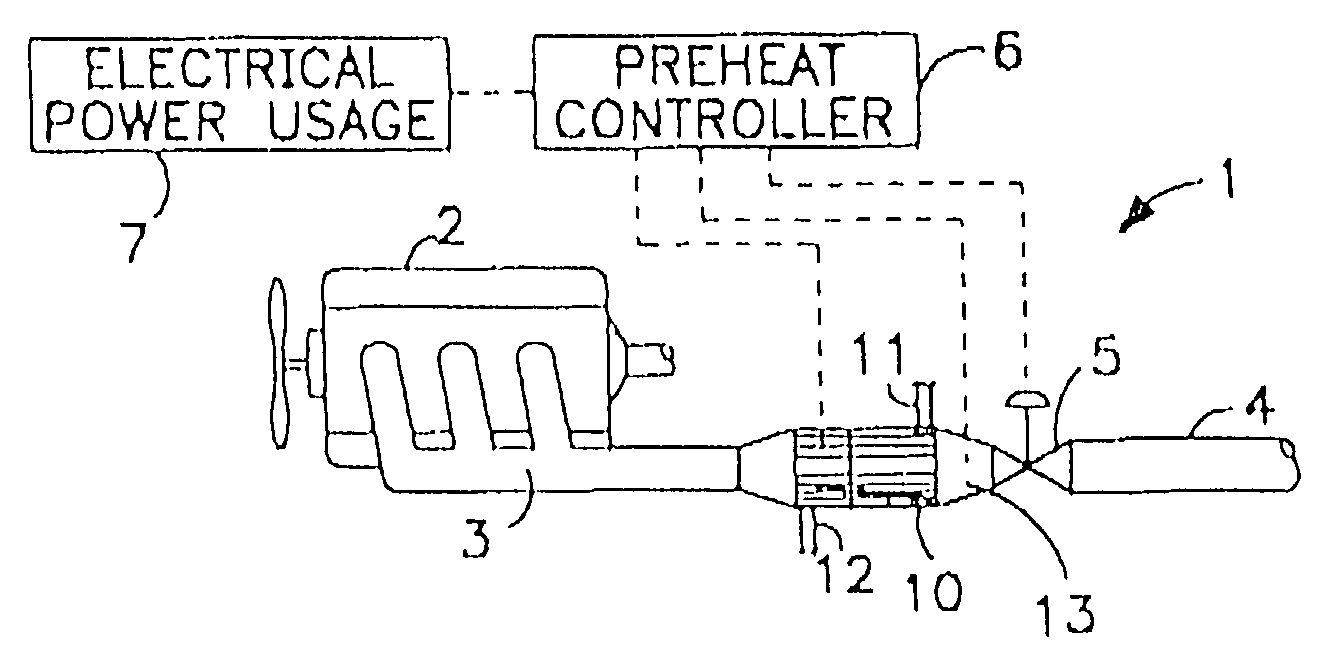
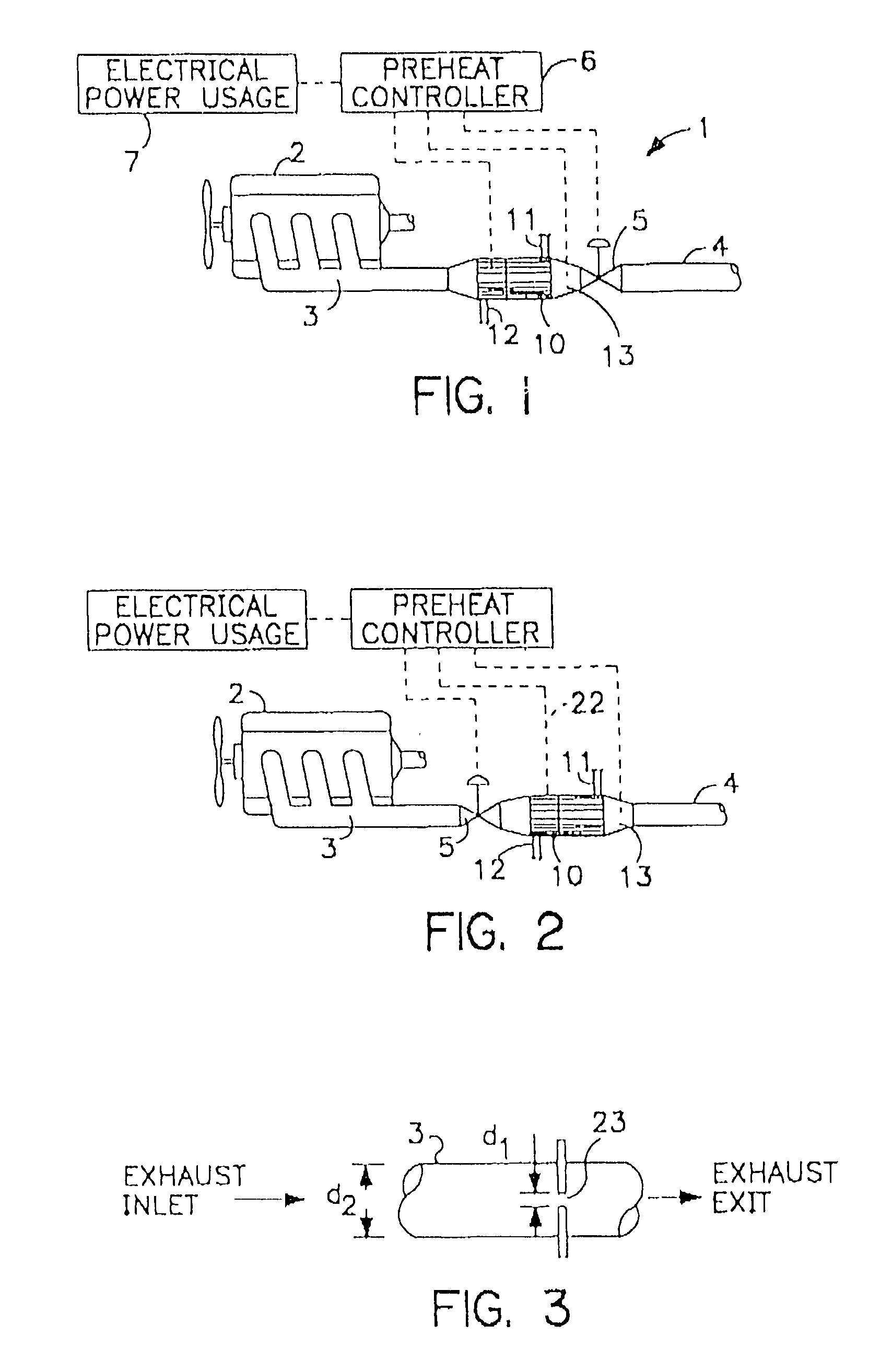
[0040]The figures that follow will better describe the operation of the thermoelectric catalytic power generator with the inclusion of an economy, or ECO, valve to increase the overall efficiency of the internal combustion engine as well as reduce the amount of pollutants that the vehicle emits.

[0041]Referring to FIG. 1 there is shown a basic layout of an exhaust system of an internal combustion engine and schematic incorporating thermoelectric catalytic power generator system 1 of the present invention. The system includes internal combustion engine 2, exhaust pipe 3, intermediate pipe 4, ECO valve 5, preheat controller 6, electric load 7, and catalytic converter 10. Catalytic converter 10 includes a coolant inlet 11, a coolant outlet 12 and temperature sensor 13 disposed inside of catalytic converter. The preheat controller receives a signal from temperature sensor 13.

[0042]Referring for the moment to FIG. 8 there is shown a cross sectional view of catalytic converter 10. For purp...


PUM

PropertyMeasurementUnit
temperatureaaaaaaaaaa

Abstract

An automobile catalytic converter that utilizes the energy of the exothermic reactions that take place in the catalysis substrate to produce electrical energy with a thermoelectric generator. On vehicle cold start, the thermoelectric generator is used as a heat pump to heat the catalyst substrate to reduce the time to catalyst light-off. In this way, the catalytic converter comes up to operating temperature more rapidly, reducing the amount of pollutant emissions at vehicle start-up.

Description

CROSS-REFERENCE TO RELATED APPLICATIONS[0001]This application is a continuation-in-part of U.S. patent application No. 09 / 419,995 filed on Oct. 18, 1999, now abandoned which is a continuation of application Ser. No. 08 / 933,663, filed Sep. 19, 1997, now U.S. Pat. No. 5,968,456, which claims the benefit of U.S. Provisional Application Ser. No. 60 / 046,027 filed May 9, 1997.BACKGROUND OF THE INVENTION[0002]1. Field of the Invention[0003]This invention relates to temperature control and power generation of a catalytic converter. More particularly this invention relates to combining the preheating of a catalytic converter and with converting the heat energy of the catalytic converter to electrical energy.[0004]2. Prior Art[0005]In an internal combustion engine vehicle, approximately 80% of the energy consumed leaves the vehicle as waste heat in various forms. For example, heat is emitted from the tailpipe, through the radiator, convected and radiated off the engine. Included with the wast...

Claims


Application Information

Patent Timeline
Patent Type & Authority Patents(United States)
IPC IPC(8): F01N3/00B01F5/06B01F13/00B29C48/33B29C48/92F01N3/20H01L35/00H01M8/04H01M10/44H01M10/50H02J7/02H02J17/00
CPCB01F5/0614B29C47/24B29C47/92F01N3/2006F01N3/2013F01N3/2046H01L35/00H01M8/04007H01M10/443H02J7/025H02J17/00Y02T10/26B01F2215/0039B29C47/0009B29C2947/92104B29C2947/926B29C2947/92704Y02E60/50B01F13/002B29C48/92B29C2948/92704B29C48/03B29C48/33B29C2948/92104B29C2948/926H02J7/34Y02A50/20Y02T10/12Y02E60/10B01F25/4314B01F33/5011B01F2101/2305H10N10/13F01N3/20H10N10/00
Inventor PARISE, RONALD J.
Owner PARISE RONALD J
Why Eureka
Try Eureka