

Basic polymer electrolyte fuel cell
- Summary
- Abstract
- Description
- Claims
- Application Information
AI Technical Summary
Benefits of technology
Problems solved by technology
Method used
Image

Examples
examples
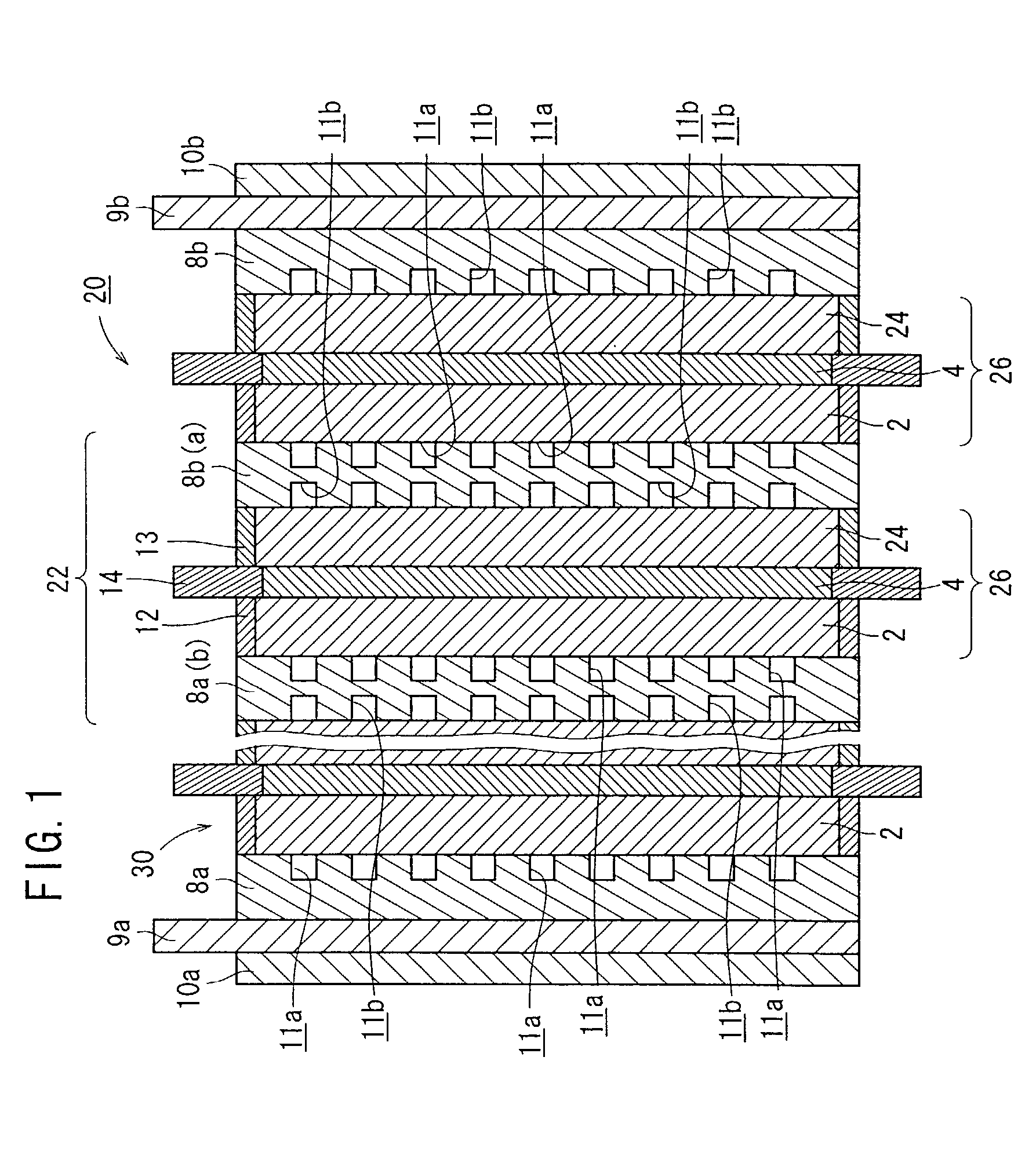
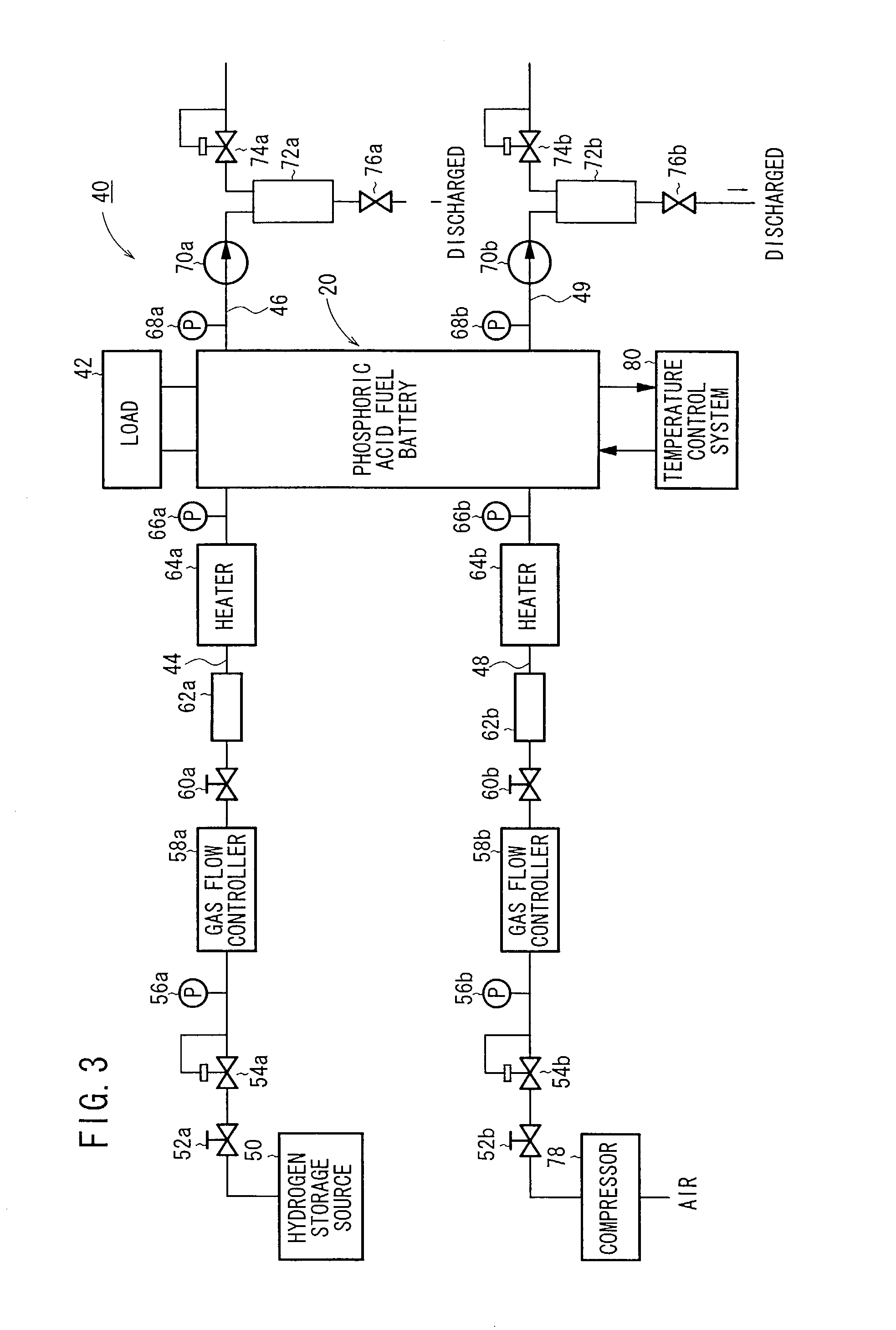
(1) Production of Fuel Cells 20
[0077]Vulcan XC72 (tradename, manufactured by Cabot Inc.) was selected as carbon black, a Pt powder was carried on the particle surface of the Vulcan XC72 at a ratio of 40 weight %, thus providing Pt-carrying Vulcan XC72 (hereinafter referred to as Pt-carrying CB).
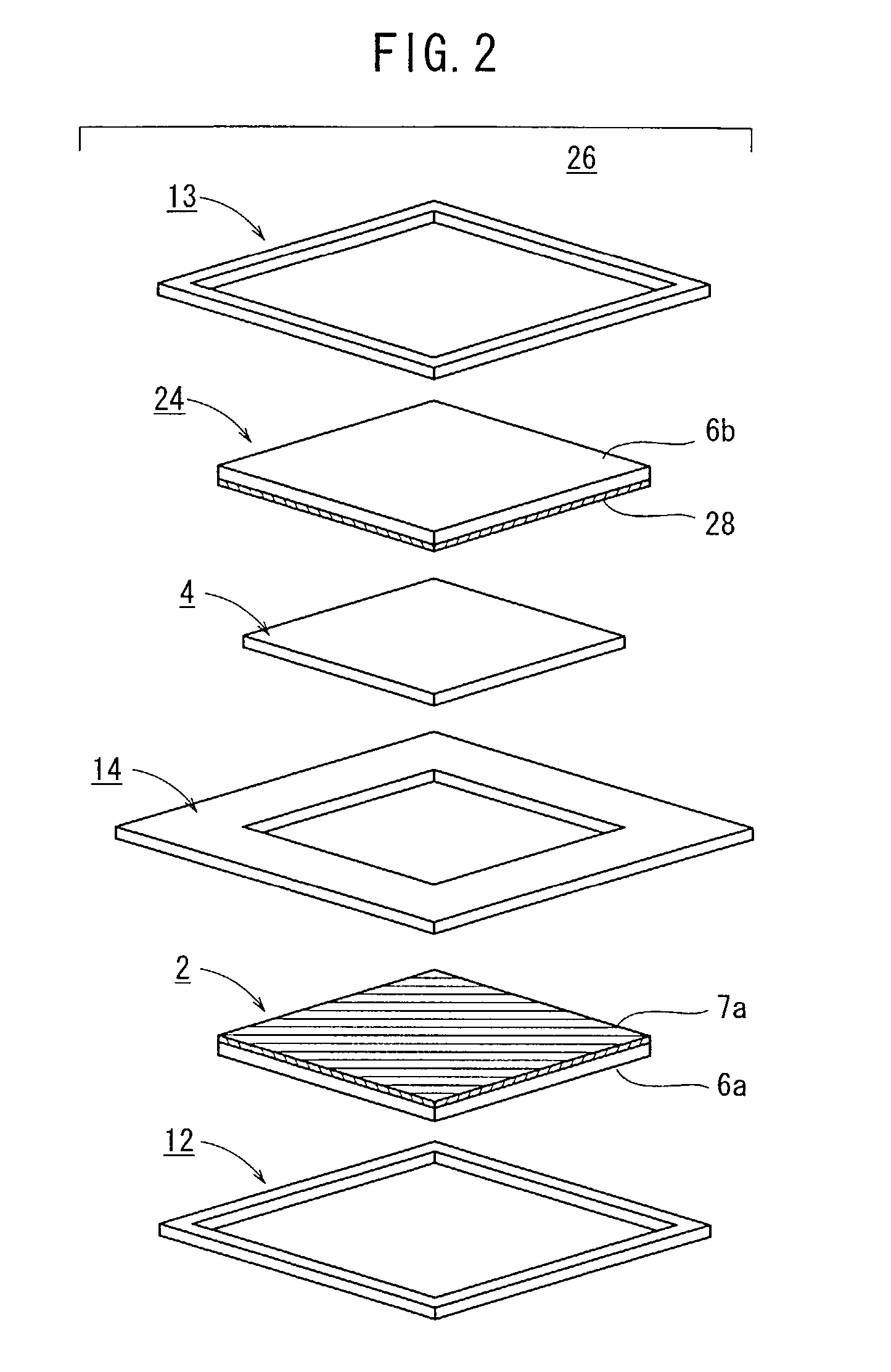
[0078]The Pt-carrying CB was dispersed in ethylene glycol to provide a dispersion, which was then coated on a piece of carbon cloth having a length of 60 mm, a width of 60 mm, and a thickness of 270 μm according to a screen printing process. The coated piece of carbon cloth was dried at 120° C. for 20 minutes to volatilize away the ethylene glycol, producing an anode electrode 2 with the Pt dispersed thereon at a ratio of 0.5 mg per 1 cm2 of carbon cloth. Specifically, the anode electrode 2 comprises a gas diffusion layer 6a made of carbon cloth and an electrode catalyst layer 7a disposed on the gas diffusion layer 6a and made of Pt-carrying CB.
[0079]Acetylene Black AB-5 (tradename, manufactu...
PUM
 Abstract
Description
Claims
Application Information