Mems-tuned high power, high efficiency, wide bandwidth power amplifier

a power amplifier and high efficiency technology, applied in the field of tuned radio frequency power amplifiers and high power high efficiency power amplifiers, can solve the problems of difficult implementation of actual matching circuits approaching matched loads over a wide frequency range at high output power levels, and operating with less than desired power amplifier efficiency across the operating frequency range. achieve the effect of high drain efficiency, high output power levels, and reduced power consumption

Inactive Publication Date: 2006-01-31
RAYTHEON CO
View PDF10 Cites 131 Cited by
  • Summary
  • Abstract
  • Description
  • Claims
  • Application Information

AI Technical Summary

Benefits of technology

[0013]With such an arrangement, it is possible to achieve high drain efficiency (greater than 80%), at relatively high output power levels for the active device, over a very wide frequency range (e.g., almost four octaves) by provi...

Problems solved by technology

Known RF systems have operated with less than desired performance in power amplifier efficiency across the operating frequency range.
The importance of providing a matched load to the output transistor for optimum efficiency has been recogniz...

Method used


Image

  • Mems-tuned high power, high efficiency, wide bandwidth power amplifier
  • Mems-tuned high power, high efficiency, wide bandwidth power amplifier
  • Mems-tuned high power, high efficiency, wide bandwidth power amplifier

Examples


Embodiment Construction

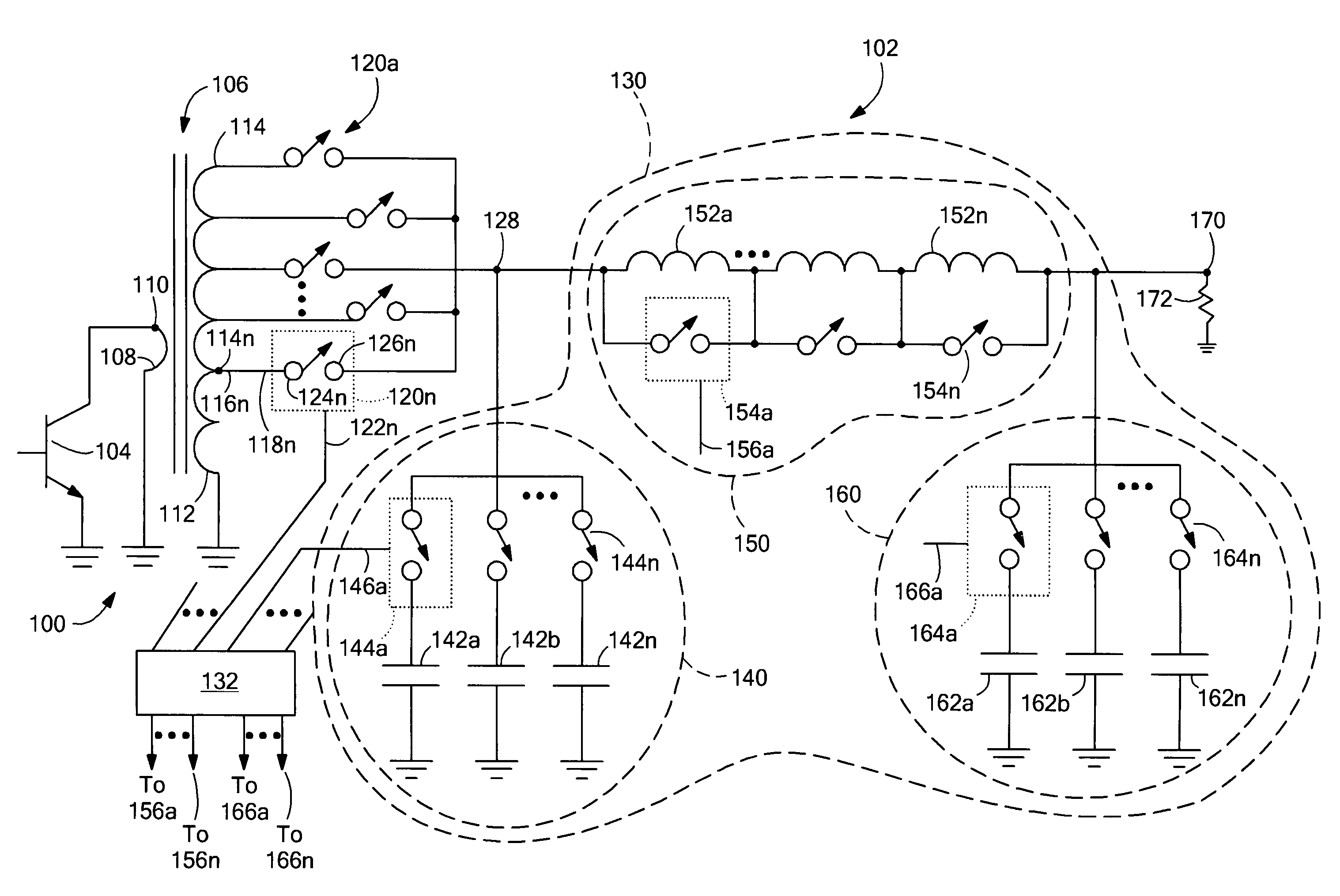
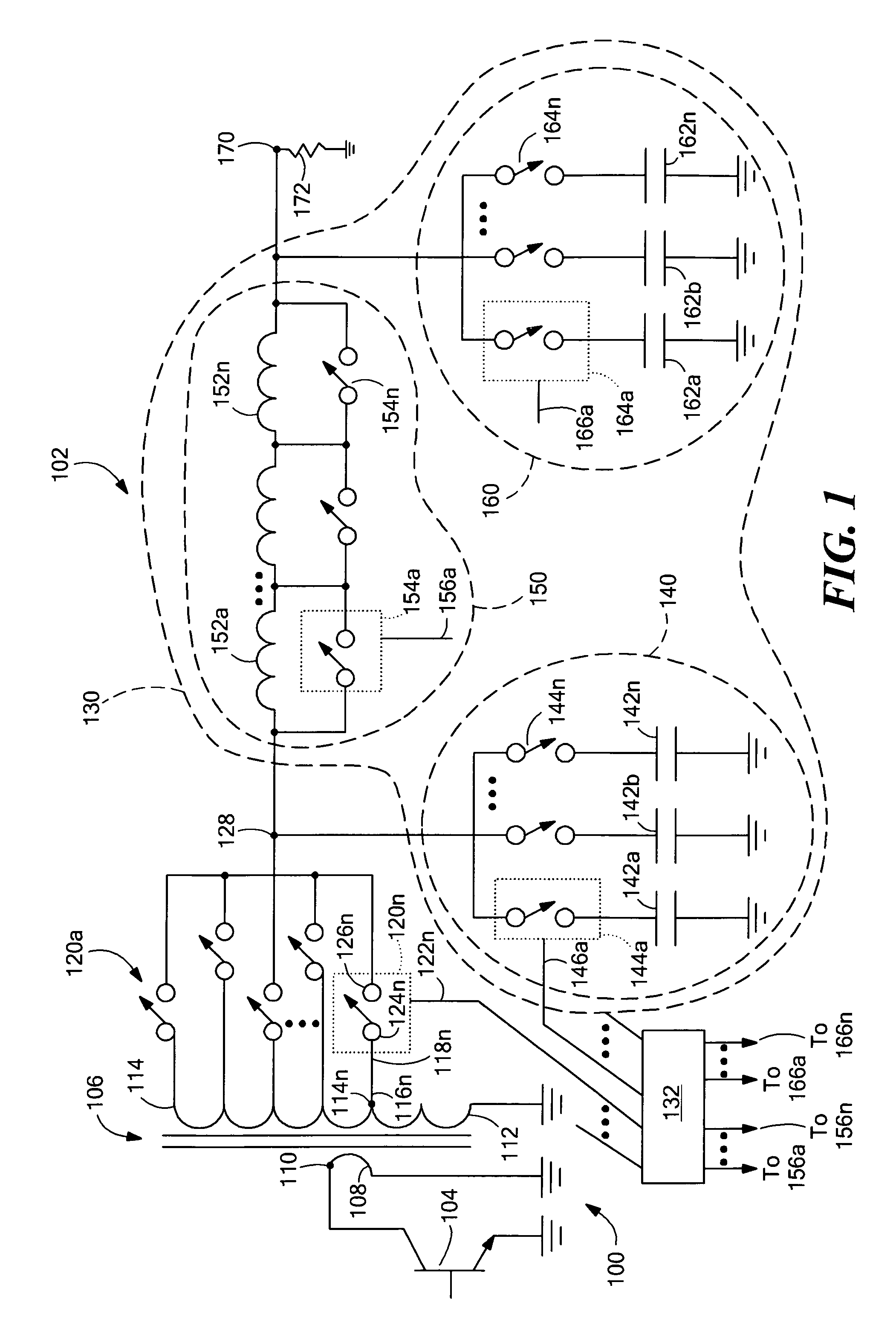
[0026]Before providing a detailed description of the invention, it may be helpful to define some of the terms used in the description. As used herein, the term “MEMS RF switch” refers to a switch or relay operated by an electrostatic charge, thermal, piezoelectric or other actuation mechanism and manufactured using micro-electromechanical fabrication techniques. MEMS RF switches are usually single pole, single throw (SPST) configurations having a rest state that is normally open. In a relay, the RF signal circuit will be electrically isolated from the control circuit, whereas in a switch the circuits may be common.

[0027]The RF power transistor technologies used in conjunction with the inventive concepts described herein include, but are not limited to, bipolar junction transistors (BJTs), silicon metal oxide semiconductor field effect transistors (Si MOSFETs), laterally diffused metal oxide semiconductor field effect transistors (LDMOS FETs), gallium arsenide metal semiconductor fie...


PUM


Abstract

A circuit for matching the impedance of an output load to an active device includes a transformer including a first winding having a terminal for coupling to the output of the active device and a second winding electromagnetically coupled to the first winding, and a plurality of taps, each of the plurality of taps having a first end coupled to a position on the second winding corresponding to a ratio of the second winding to first winding differing from other ones of the plurality of taps, and a second end. The matching circuit further includes a plurality of MEMS switches each having a control input for receiving a corresponding control signal, a first terminal coupled to the second end of a corresponding one of the plurality of taps, and a switched output selectively coupled to a matching junction in response to the corresponding control signal.

Description

CROSS-REFERENCE TO RELATED APPLICATIONS[0001]Not applicable.STATEMENTS REGARDING FEDERALLY SPONSORED RESEARCH[0002]Not applicable.FIELD OF THE INVENTION[0003]This invention relates generally to tuned radio frequency power amplifiers, high power high efficiency power amplifiers, and more particularly to tunable high power high efficiency power amplifiers.BACKGROUND OF THE INVENTION[0004]In wireless radio frequency (RF) communications and radar applications, it is often desirable to provide power amplifiers having high power over a wide frequency range. Transistor power amplifiers operating at high output power over wide instantaneous bandwidths typically tradeoff efficiency (RF power output divided by DC power input) for acceptable power output and gain performance across a predetermined frequency range. This tradeoff is required because the optimum load impedance for the output transistor is not presented to the transistor at each frequency within the operating range. Instead, a loa...

Claims


Application Information

Patent Timeline
IPC IPC(8): H03H7/38H03F1/56H03F3/191
CPCH03F1/56H03F3/191H03H7/38H03F2200/391H03F2200/451H03F2200/541H03F2200/421
Inventor LUETZELSCHWAB, ROLAND C.STREETER, ROBERT D.MCMILLAN, LEE A.
Owner RAYTHEON CO
Why Eureka
Try Eureka