Control system with capacitive detector

a capacitive detector and control system technology, applied in the direction of resistance/reactance/impedence, instruments, pulse techniques, etc., to achieve the effect of enhancing sensitivity and hence sensor range, and reducing capacitan

Inactive Publication Date: 2006-02-07
GERENRAICH FAMILY TRUST
View PDF19 Cites 58 Cited by
  • Summary
  • Abstract
  • Description
  • Claims
  • Application Information

AI Technical Summary

Benefits of technology

[0033]Preferably a grounded shield electrode is also provided and disposed in a spaced apart relationship parallel to and above the sense electrodes. This eliminates the sensing electric field in the region above the shield in order that that region may be utilized without falsely activating the system. In an alternative embodiment the shield...

Problems solved by technology

This is hence contrary to the known prior art systems ...

Method used


Image

  • Control system with capacitive detector
  • Control system with capacitive detector
  • Control system with capacitive detector

Examples


Embodiment Construction

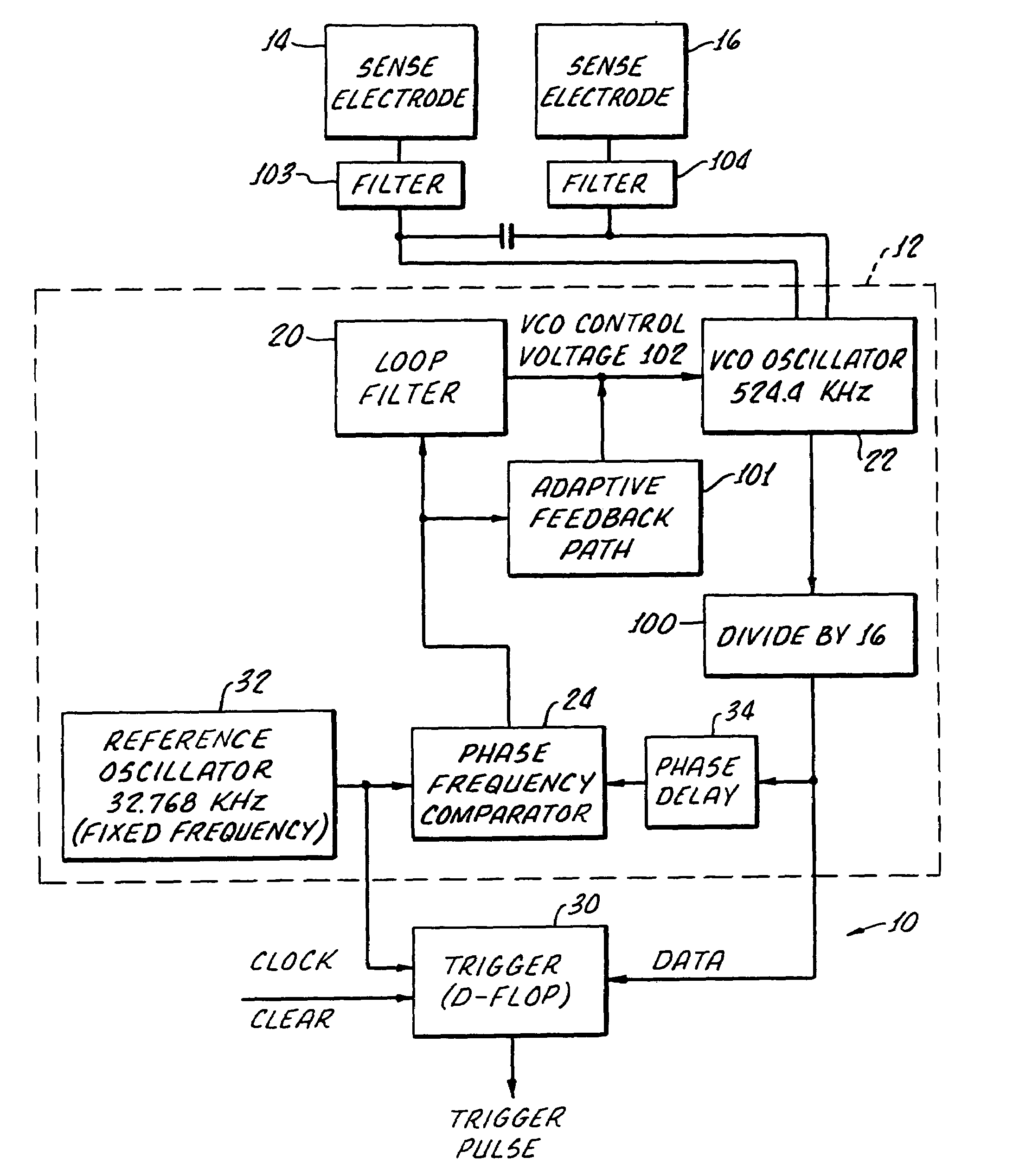
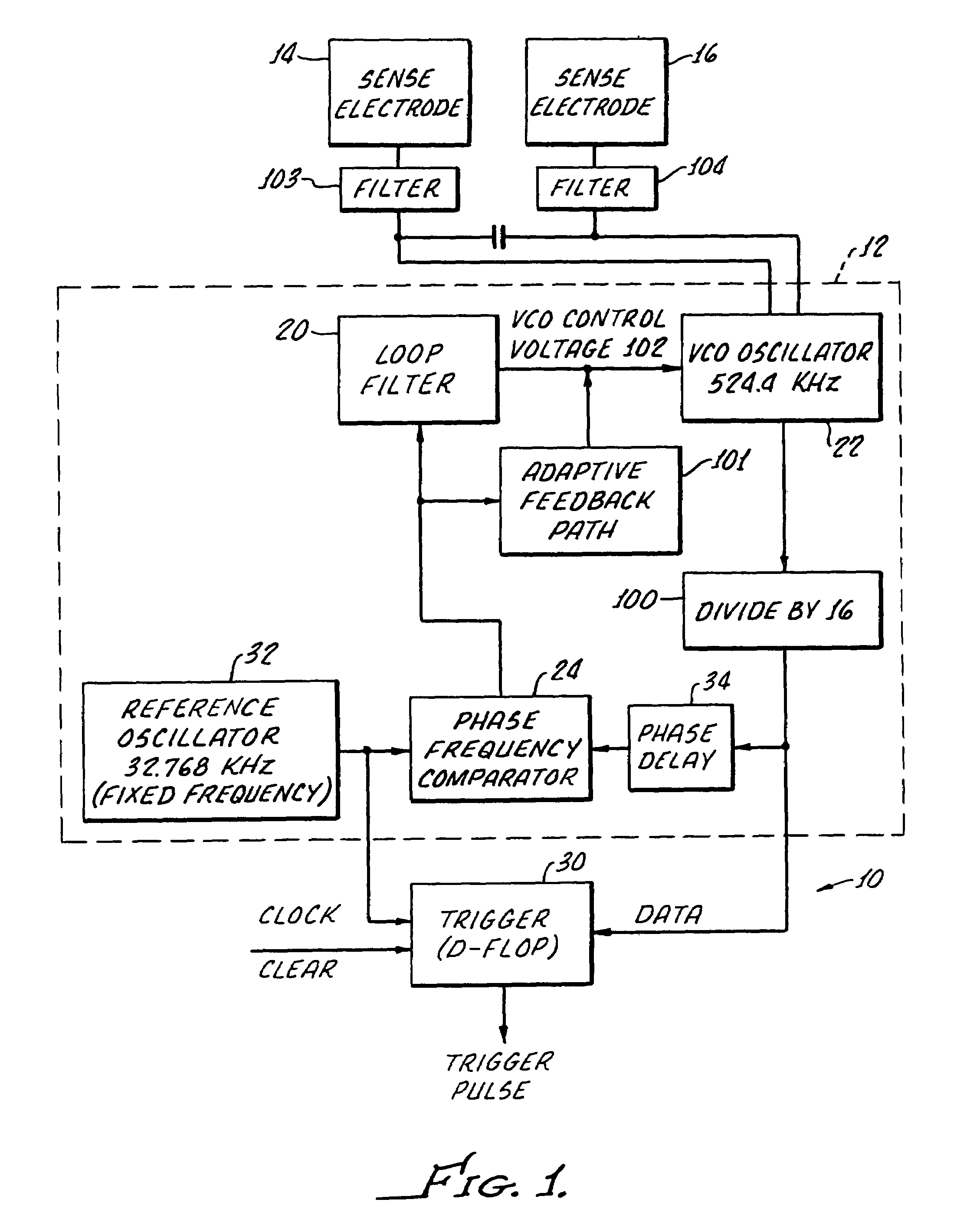
[0040]With reference to FIG. 1 there is shown a block diagram of sensor electronics 10 in accordance with the present invention. The circuit set forth is an example of electronic circuitry for providing a control output signal in response to a rate of change in capacitance of the sense electrodes due to motion of the proximate object within the field without intermediate electronic differentiation of signals related to a change in capacitance.

[0041]The overall principle of operation is as follows: A phase locked frequency control loop (PLL) 12 is interconnected with sense electrodes 14 and 16. The PLL includes a voltage controlled oscillator (VCO) 22 which has an output, the frequency of which is linearly related to the input control voltage 102. The output is connected to a phase / frequency comparator via a frequency divider 100 and a fixed phase delay network 34.

[0042]A reference oscillator 32 is also connected to the comparator and generates a continuous fixed frequency signal. Th...


PUM


Abstract

A capacitive sensor system for controlling operation of a device in response to a rate of change in capacitance due to motion of a proximate object includes at least two sense electrodes disposed on a surface and a phase locked loop, including a voltage controlled oscillator and a phase/frequency comparator, connected between the sense electrodes and an RC network for providing an operating frequency to the sense electrodes. A circuit loop, including a reference oscillator, provides a fixed frequency reference for the phase locked loop to follow and a phase delay circuit connected between the phase/frequency comparator and the voltage controlled oscillator causes the voltage controlled oscillator to run ahead of the reference oscillator. A trigger circuit provides a control output in response to a change in phase shift between the fixed frequency and the operating frequency.

Description

[0001]The present application is a continuation of U.S. Ser. No. 10 / 062,866 filed Jan. 30, 2002, now U.S. Pat. No. 6,731,209 B2 which is a continuation of provisional patent application Ser. No. 60 / 267,113 filed Feb. 7, 2001.[0002]The present invention is generally related to automatic control systems and is more particularly directed to a system for controlling operation of a device utilizing a capacitive sensor.BACKGROUND[0003]A great number of capacitive sensors have been heretofore developed for the sensing of persons or materials to provide an alarm, indicating signal, or control. For example, capacitive sensing circuits have been used for alarm systems to provide a signal in response to touching of a particular area or the proximity of an object. In other instances, capacitive sensing circuits have been utilized to detect the presence or absence of liquids and solids and thereafter initiating an indicator for alarm signals or measurement. Capacitive sensors have also been used...

Claims


Application Information

Patent Timeline
IPC IPC(8): G08B13/26G01N27/22G01D5/24H03K17/955
CPCG01D5/24H03K17/955G08B13/26G01R27/26
Inventor WADLOW, DAVIDSCHOLTEN, FRANKGIFFONE, RALPHGERENRAICH, KENNETH
Owner GERENRAICH FAMILY TRUST
Why Eureka
Try Eureka