Method and apparatus for radiation analysis and encoder

a radiation analyzer and encoder technology, applied in the field of radiation spectrum analyzers and radiation image analyzers, can solve the problems of large, heavy, non-portable, unnecessary data, and inability to adapt to the number of spectral components which can be analyzed, and achieve the effect of compact fluorescence, fast and compact fluorescence, and increasing the spatial or spectral resolution of the analyzer

Inactive Publication Date: 2006-02-14
MUDLOGGING SYST
View PDF32 Cites 22 Cited by
  • Summary
  • Abstract
  • Description
  • Claims
  • Application Information

AI Technical Summary

Benefits of technology

[0008]This invention provides many advantages over the radiation analyzers described above in that the intensity of the incident radiation is modulated independent of the bandwidth and that the amplitude of the modulated signal is a smooth function or changes between three or more distinct levels of contrast as the modulator is rotated about an axis or otherwise reciprocated. Using the present invention, one can implement a multi-channel orthogonal encoding scheme for arbitrary center wavelengths and bandwidths and arbitrary radial intensity distributions. In this manner, the center wavelengths and bandwidths of the encoded channels can be independently optimized for a specific application. The present invention combines the before mentioned optical encoding scheme with imaging optics so that radiation from an extended source or collection of discrete samples can be imaged using a single detector. The present invention allows one to control the modulation depth on a channel-by-channel basis independent of the bandwidth, a design strategy which may be useful for balancing signal levels in systems where one or more channels have a disproportionately large fraction of the total incident radiation. The present invention allows one to group modulation channels into complementary pairs where the amplitude and phase of the resulting encoded component is determined by the relative portion of radiation incident on the two filters comprising the pair. In this manner, intensity differences, wa

Problems solved by technology

While these analyzers offer superior spectral performance, they tend to be expensive, large, heavy and non portable.
The processing of the additional, unnecessary data reduces the speed of these instruments.
As a consequence, the non-dispersive approach has clear limitation in adaptability and the number of spectral components which can be analyzed.
This set of simultaneous equations is then solved to yield the intensity for each channel prior to any specific analytical function, an approach which is time consuming and prone to errors.
Furthermore, as a direct consequence of the binary encoding approach, there is no mechanism by which one can recover the actual signal levels if any one of the signal levels changes substantially over the period of rotation.
However, this approach changes t

Method used


Image

  • Method and apparatus for radiation analysis and encoder
  • Method and apparatus for radiation analysis and encoder
  • Method and apparatus for radiation analysis and encoder

Examples


example 1

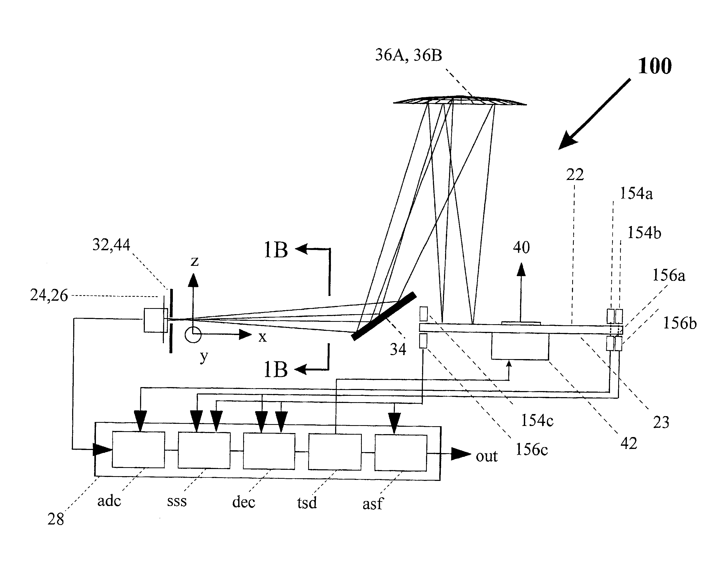
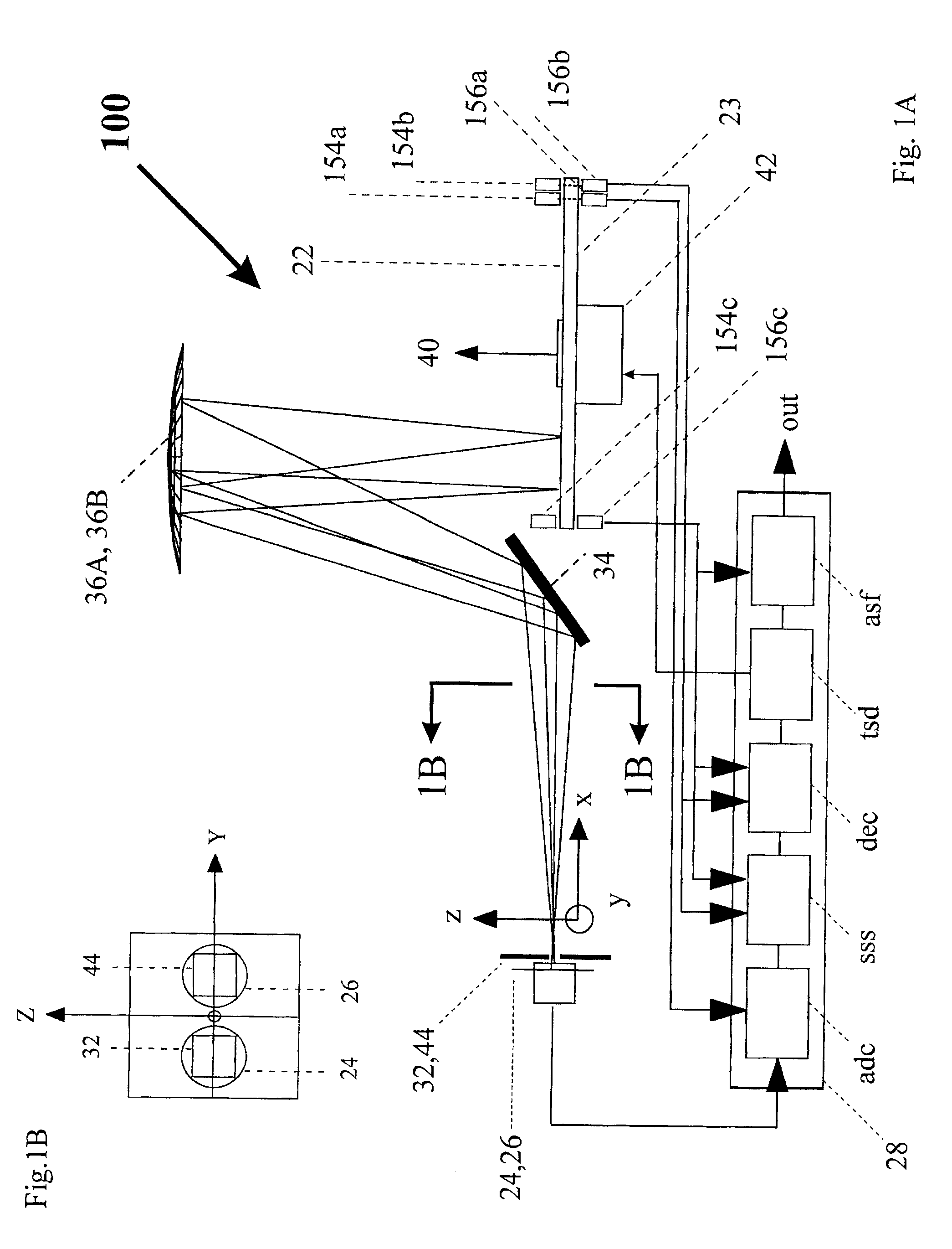
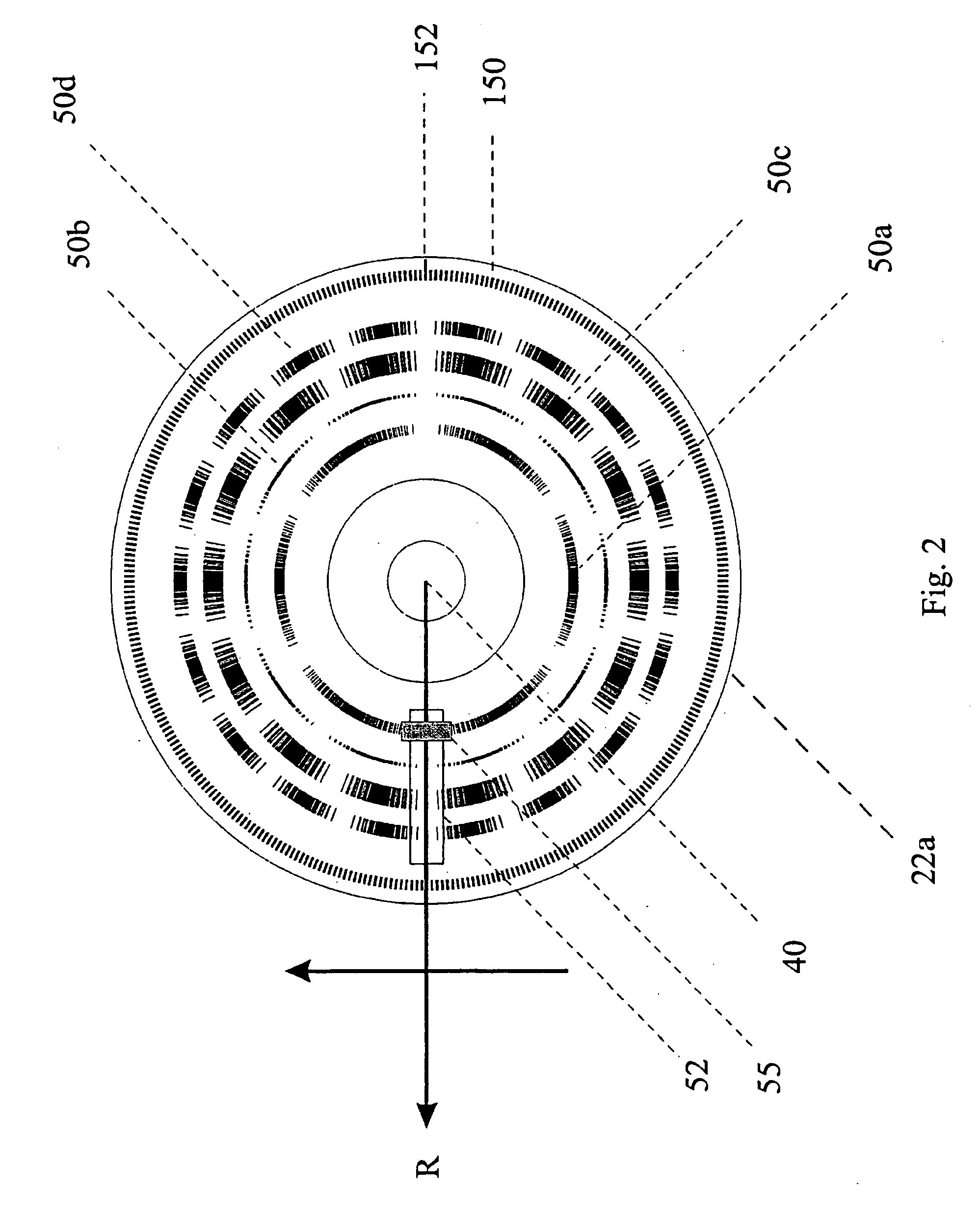
[0114]The first example of the dual-use analyzer 100 depicted in FIG. 1, analyzer 100.1, is a multi-spectral-component encoded source with a high-intensity, collimated beam which can be used to excite radiation emitting samples, or to measure absorbing gasses and vapors over a large distance, or to probe optically dense media such as liquids or solids. Radiation source 24.1 is a collimated radiation beam having a plurality of selected spectral components (e.g., an argon-ion or a carbon dioxide laser). Pre-encoder optic 36A.1 includes a diffractive or refractive element to separate the selected spectral components to form a target image along a radial axis of modulator 22.1. Preferably, pre-encoder optic 36A.1 includes a variable attenuator to precondition or preset the intensities of the selected components. Target image 52.1 is a dispersed image comprised of selected spectral components focused at substantially different points along said radial axis of modulator 22.1. Modulator 22...

example 2

[0116]The second example of the dual-use analyzer 100 depicted in FIG. 1, analyzer 100.2, is compact spectrum analyzer which uses a collection of bandpass filters or a linear variable filter (LVF) to provide a plurality of selected radiation components. In analyzer 100.2, the radiation source is comprised of a broad band or multi-wavelength source filtered by a linear array of two or more bandpass filters or a linear variable filter (LVF). Taken together the radiation source and the collection of bandpass filters or LVF comprise extended source 24.2, having a number of spatial components corresponding to the radiation transmitted through (or reflected from) the individual bandpass filters or specific positions along the LVF. The radiation filtered by the array of bandpass filters or LVF is imaged by pre-encoder optic 36A.2 to form target image 52.2 substantially along a radial axis of modulator 22.2. Target image 52.2 is comprised of the sub-images of the radiation transmitted throu...

example 3

[0118]The third example of the dual-use analyzer 100 depicted in FIG. 1, analyzer 100.3, is a spectrum analyzer, which is used for both analyzing and providing feedback to simultaneously control the center wavelengths of a number of tunable radiation sources. Radiation source 24.3 is comprised of a plurality of spectral components, where each spectral component corresponds to a distinct radiation source and is characterized by an intensity and a center wavelength. For example, radiation source 24.3 may be an optical fiber containing a plurality of optical signals, where each signal corresponds to a different radiation source. Radiation emitted by source 24.3 is imaged by pre-encoder optic 36A.3 to form a target image 52.3 onto modulator 22.3. Target image 52.3 is comprised of a plurality of sub-images focused at substantially different points along a radial axis of modulator 22.3, where each sub-image corresponds to a distinct radiation source. Pre-encoder optic 36A.3 is comprised o...


PUM


Abstract

Method and apparatus for analyzing radiation using analyzers and encoders employing the spatial modulation of radiation dispersed by wavelength or imaged along a line.

Description

CROSS REFERENCE TO RELATED APPLICATION[0001]This application is a continuation-in-part of co-pending U.S. patent application Ser. No. 09 / 105,279, filed Jun. 26, 1998 now U.S. Pat. No. 6,271,917, International Application Ser. No. PCT / US99 / 14446, filed Jun. 25, 1999, and of U.S. Provisional Application Ser. No. 60 / 202,371, filed May 4, 2000.BACKGROUND OF THE INVENTION[0002]This invention relates in general to radiation spectrum analyzers and radiation image analyzers, and in particular, to radiation analyzers and encoders employing the spatial modulation of radiation dispersed by wavelength or imaged along a line.[0003]Radiation spectral analysis is presently carried out in a number of ways. Dispersive and Fourier transform based analyzers are for high resolution and can be used for many different applications so that they are more versatile than existing application-specific instruments and procedures. While these analyzers offer superior spectral performance, they tend to be expens...

Claims


Application Information

Patent Timeline
IPC IPC(8): G01J3/04G02B26/02G01J3/12G01J3/28G01J3/32G01J3/433
CPCG01J3/02G01J3/021G01J3/0229G01J3/12G01J3/2846G01J3/32G01N21/6456G01J3/433G01N2021/6471G01J2001/4242G01J2003/2866G01N2021/6417G01N2021/6423G01N2021/6463
Inventor HAGLER, THOMAS W.
Owner MUDLOGGING SYST
Why Eureka
Try Eureka