
Fiber transmission element for generating a chromatic dispersion

a transmission element and fiber technology, applied in the direction of optics, instruments, optical light guides, etc., can solve the problems of occupying a large space, high cost, and a large amount of space, and achieve the effect of improving the coupling effect of different modes in fiber bragg gratings

Inactive Publication Date: 2006-02-14
THORLABS INC
View PDF11 Cites 20 Cited by
  • Summary
  • Abstract
  • Description
  • Claims
  • Application Information

AI Technical Summary

Benefits of technology

[0013]The object of the invention is to specify a component which produces specific, normal or anormal dispersion, which can be predetermined, with a small physical size and with low cost, and whose losses are as low as possible.
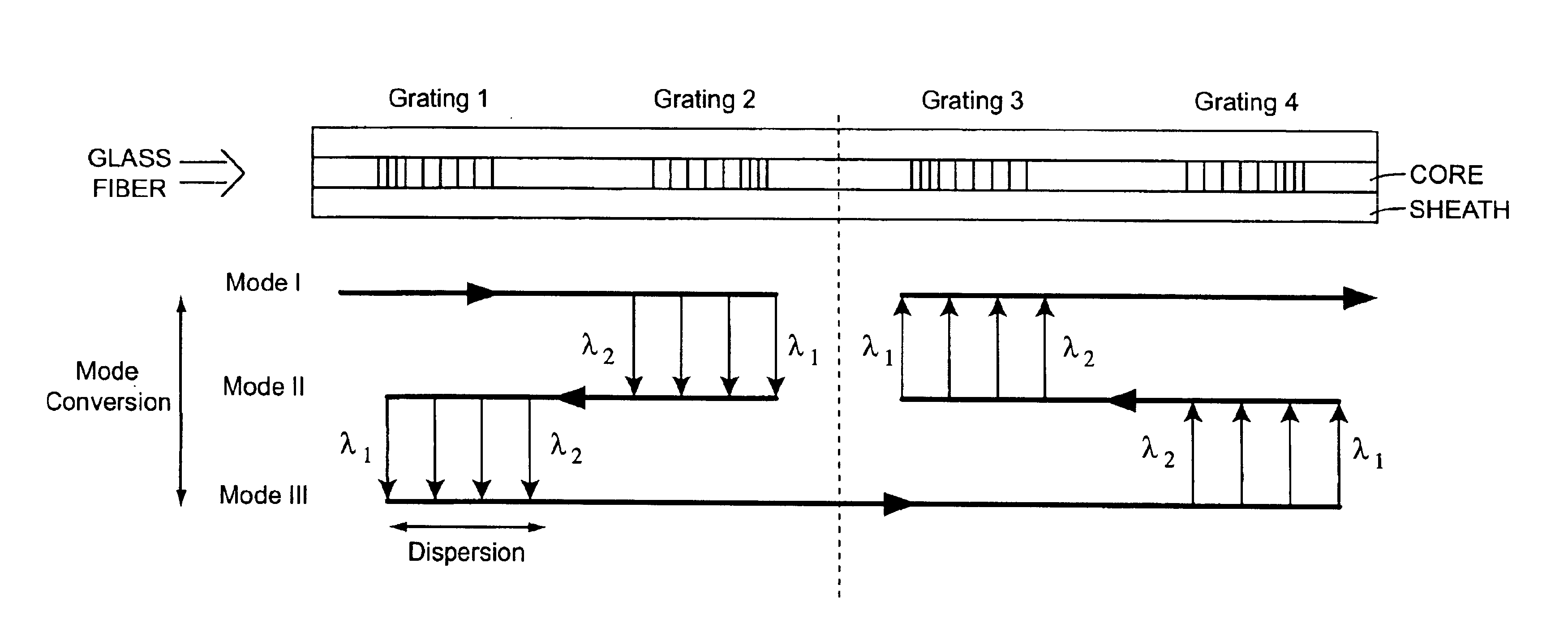
[0017]If the first chirped fiber Bragg grating has the larger grating constant on the input side and the smaller grating constant on the output side, then the propagation time difference increases as the wavelength becomes shorter. If the chirp direction of one grating or the other is reversed, then the propagation time difference increases as the wavelength becomes longer. It is thus possible to select the chirp direction in order to set whether the component according to the invention is intended to compensate for normal or anormal dispersion of an upstream or downward element and, in particular, of a transmission path. Suitable choice of the chirp profile also makes it possible to achieve a transition from normal to anormal dispersion.
[0023]The rotationally symmetrical modes LP02 and LP03 are advantageously used in the multimode glass fiber optical waveguide. However, non-rotationally-symmetrical modes, such as the LP11 mode, may also be used. Then, the fiber Bragg gratings must be produced slightly obliquely with respect to the fiber axis. In addition to the two carried modes, a cladding mode may also be used. In comparison to the proposal quoted in the cited presentation by P. Petruzzi et al., mode coupling between cladding modes is avoided, so that this results in considerably better coupling efficiency.
[0025]The coupling effectiveness of different modes in fiber Bragg gratings can be improved if, in addition to radial regions with the normal GeO2 doping, regions with F-and / or B2O3 doping are also used.

Problems solved by technology

These have the disadvantage that, owing to the required length, they occupy a large amount of space and are very expensive.
A disadvantage of the compensation element which is disclosed in DE 35 24 527 A1 is that the reflected signal to which the dispersion is applied is branched off through a 3 dB fiber coupler or, according to the description in this document, preferably through a circulator.
The additional 3 dB fiber coupler has a serious disadvantage of a 6 dB optical power loss, corresponding to a 12 dB electrical power loss.
The circulator is once again an expensive additional element.
However, only modest results can be expected, in comparison to reflection on chirped gratings.
A first disadvantage, which is also stated at least for the present experimental configuration, is the low coupling efficiency to the cladding modes and, in particular, also the coupling efficiency between the cladding modes.
A second disadvantage is the use of the two cladding modes, since these are very much more severely influenced by environmental effects, and in particular by fiber curvature, than carried modes.
A further disadvantage is the use of a long-period grating, whose filter characteristic cannot be coped with as well as that of the Bragg gratings, and which require considerably long physical lengths.

Method used


Image

  • Fiber transmission element for generating a chromatic dispersion
  • Fiber transmission element for generating a chromatic dispersion

Examples


Embodiment Construction

[0013]The object of the invention is to specify a component which produces specific, normal or anormal dispersion, which can be predetermined, with a small physical size and with low cost, and whose losses are as low as possible.

[0014]One solution of this object, according to the invention, is specified in patent claim 1. Developments of the invention and an application are the subject matter of claim 2 and the subsequent claims.

[0015]According to the invention, a transmission component is provided for producing (positive or negative) chromatic dispersion which can be predetermined and is suitable, for example, for compensating for the dispersion in a glass fiber optical waveguide. Not only the LP01 fundamental mode, but also at least one LPmn mode can be carried in the component according to the invention. To this end, the transmission component according to the invention has two pairs of Bragg gratings, of which, for example, each pair may have at least one chirped Bragg grating. ...


PUM


Abstract

The invention describes a transmission component for producing chromatic dispersion which can be predetermined, havinga glass fiber optical waveguide in which it is possible to carry not only the LP01 fundamental mode but also at least one LPmn mode, andtwo pairs of Bragg gratings (gratings 1 and 2, as well as 3 and 4), of which at least one pair has chirped Bragg gratings,in which the first Bragg grating in each pair reflects the arriving light beam back to the other Bragg grating in a direction approximately opposite the incidence direction, and from which other Bragg grating the light beam emerges in, or at least parallel to, the original incidence direction.

Description

TECHNICAL FIELD[0001]The invention relates to a transmission component for producing chromatic dispersion.[0002]For the wavelength band of an erbium fiber amplifier, for example, that is to say for wavelengths x around 1550 nm, standard fibers have anormal dispersion with a dispersion parameter of D≈17 ps per nm of bandwidth and per km of fiber length. In order to compensate for this—disturbing—dispersion, it is necessary to use components with opposite, that is to say normal, dispersion (negative dispersion parameter D) of suitable magnitude, matched to the length of the standard fiber to be compensated.PRIOR ART[0003]Until now, compensation fibers have been used in practice to produce negative dispersion of a magnitude which is suitable to compensate for the dispersion of standard fibers and, in particular, of glass fibers. These have the disadvantage that, owing to the required length, they occupy a large amount of space and are very expensive.[0004]DE 35 24 527 A1 discloses the ...

Claims


Application Information

Patent Timeline
Patent Type & Authority Patents(United States)
IPC IPC(8): G02B6/34G02B6/13G02B6/02G02B6/14
CPCG02B6/14G02B6/29394G02B6/29319
Inventor NOWAK, WALTERPEUPELMANN, JENSSAUER, MICHAELBAUMANN, INGOLFMEISSNER, JOHANNPALME, DIETERBANDEMER, ADALBERT
Owner THORLABS INC
Learn More