
Lithographic apparatus and device manufacturing method

a technology of lithographic apparatus and manufacturing method, which is applied in the direction of printers, photographic processes, instruments, etc., can solve the problems of difficult control and accuracy, and achieve the effects of accurate control, accurate edge placement, and easy control

Active Publication Date: 2006-02-21
ASML NETHERLANDS BV
View PDF23 Cites 4 Cited by
  • Summary
  • Abstract
  • Description
  • Claims
  • Application Information

AI Technical Summary

Benefits of technology

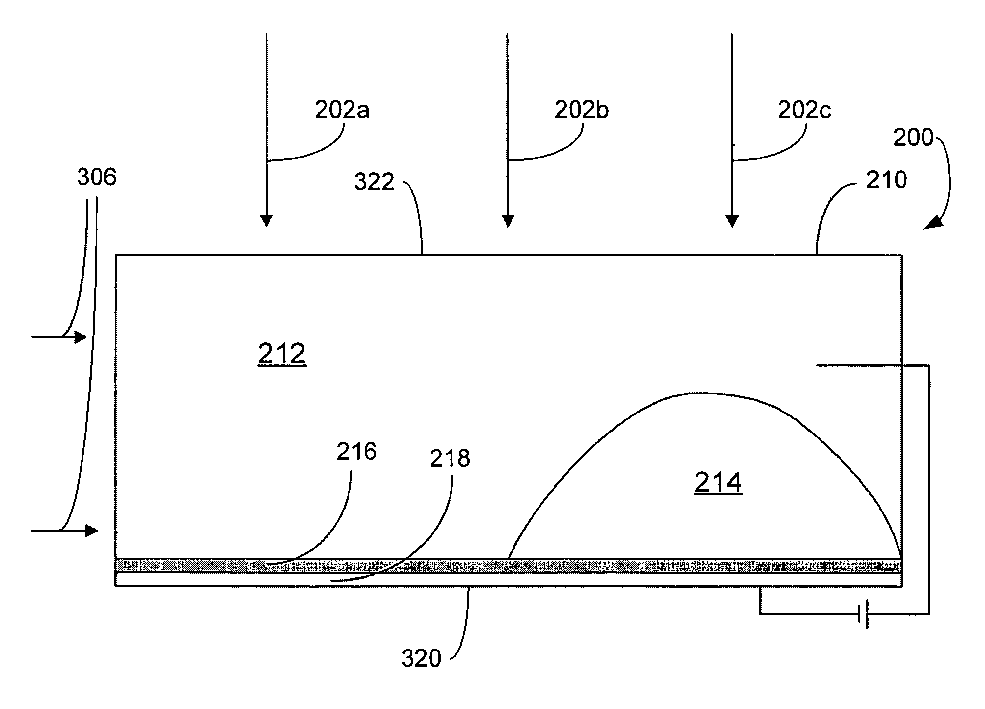
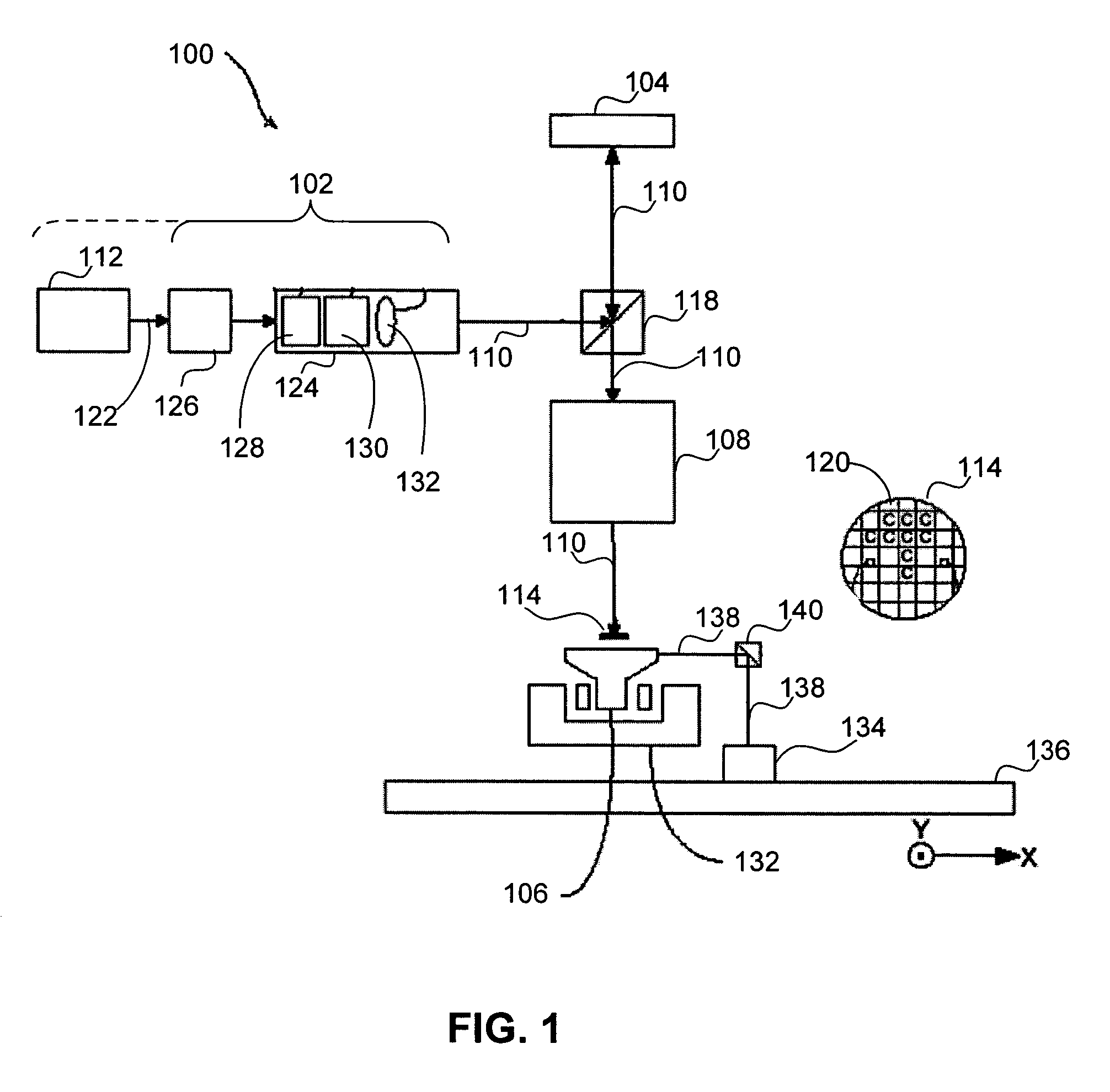
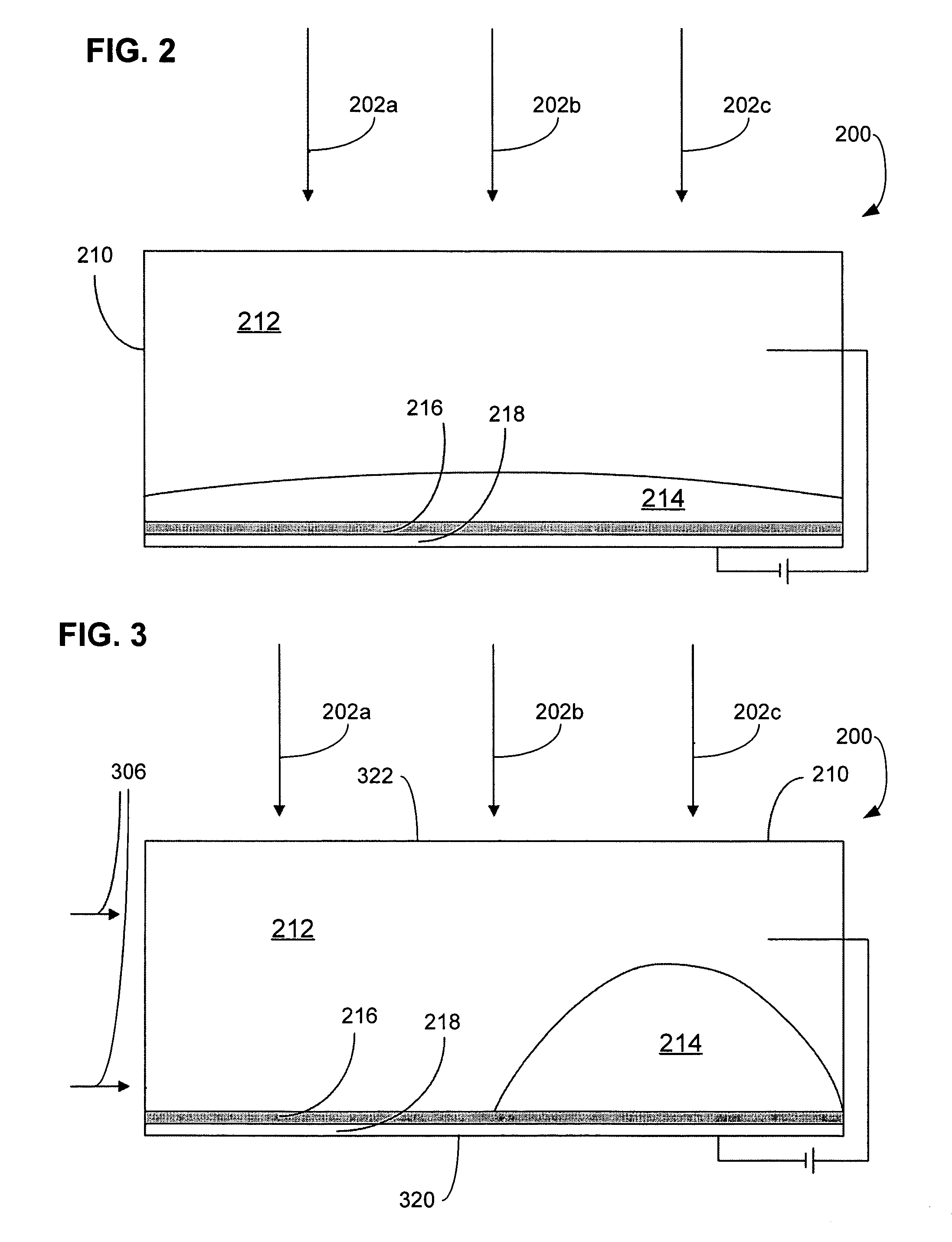
The present invention provides a lithographic apparatus that uses a patterning array with individually controllable elements to impart a pattern onto a substrate. The apparatus includes an illumination system, a patterning array, a substrate table, and a projection system. The individually controllable elements each contain a polar fluid and a non-polar fluid, which have different refractive indices. The non-polar fluid is displaced by an electric field to change the phase of the projected beam. The apparatus allows for accurate edge placement without loss of pattern and can be controlled accurately without the need for actuators. The relative properties of the polar and non-polar fluids are chosen to change the phase of the projected beam as desired. The apparatus also includes a reflective surface to change the phase of the projected beam twice. The invention also provides a method for manufacturing a device using the lithographic apparatus.

Problems solved by technology

Thus, there is no need for actuators, which can be bulky and difficult to control accurately.

Method used


Image

  • Lithographic apparatus and device manufacturing method
  • Lithographic apparatus and device manufacturing method
  • Lithographic apparatus and device manufacturing method

Examples


Embodiment Construction

Overview and Terminology

[0021]The term “array of individually controllable elements” as here employed should be broadly interpreted as referring to any device that can be used to endow an incoming radiation beam with a patterned cross-section, so that a desired pattern can be created in a target portion of the substrate. The terms “light valve” and “Spatial Light Modulator” (SLM) can also be used in this context. Examples of such patterning devices are discussed below.

[0022]A programmable mirror array may comprise a matrix-addressable surface having a viscoelastic control layer and a reflective surface. The basic principle behind such an apparatus is that, for example, addressed areas of the reflective surface reflect incident light as diffracted light, whereas unaddressed areas reflect incident light as undiffracted light. Using an appropriate spatial filter, the undiffracted light can be filtered out of the reflected beam, leaving only the diffracted light to reach the substrate. ...


PUM

PropertyMeasurementUnit
wavelengthaaaaaaaaaa

Abstract

A lithographic apparatus includes a patterning device that patterns a projected beam. The patterning device includes an array of cells that contain a polar fluid, a non-polar fluid, and an electrode. A potential difference across the electrode and the polar fluid causes displacement of the non-polar fluid. Based on a difference in refractive index between the polar fluid and the non-polar fluid, a beam of light which passes through the cell will have its phase changed in dependence on the relative thickness on the polar and non-polar fluids and on their refractive indices.

Description

BACKGROUND OF THE INVENTION[0001]1. Field of the Invention[0002]The present invention relates to a lithographic apparatus and a device manufacturing method.[0003]2. Related Art[0004]A lithographic apparatus is a machine that applies a desired pattern onto a target portion of a substrate. The lithographic apparatus can be used, for example, in the manufacture of integrated circuits (ICs), flat panel displays and other devices involving fine structures. In a conventional lithographic apparatus, a patterning device, which is alternatively referred to as a mask or a reticle, may be used to generate a circuit pattern corresponding to an individual layer of the IC (or other device). This pattern can be imaged onto a target portion (e.g., part of one or several dies) on a substrate (e.g., a silicon wafer or glass plate) that has a layer of radiation-sensitive material (e.g., resist). Instead of a mask, the patterning device may comprise an array of individually controllable elements that g...

Claims


Application Information

Patent Timeline
Patent Type & Authority Patents(United States)
IPC IPC(8): G03B27/42G02F1/07G03B27/32G03B27/54G03C5/00G02B26/08G02B27/00G03F7/20H01L21/027
CPCG03F7/70291G03F7/70283
Inventor BLEEKER, ARNO J.
Owner ASML NETHERLANDS BV
Learn More