

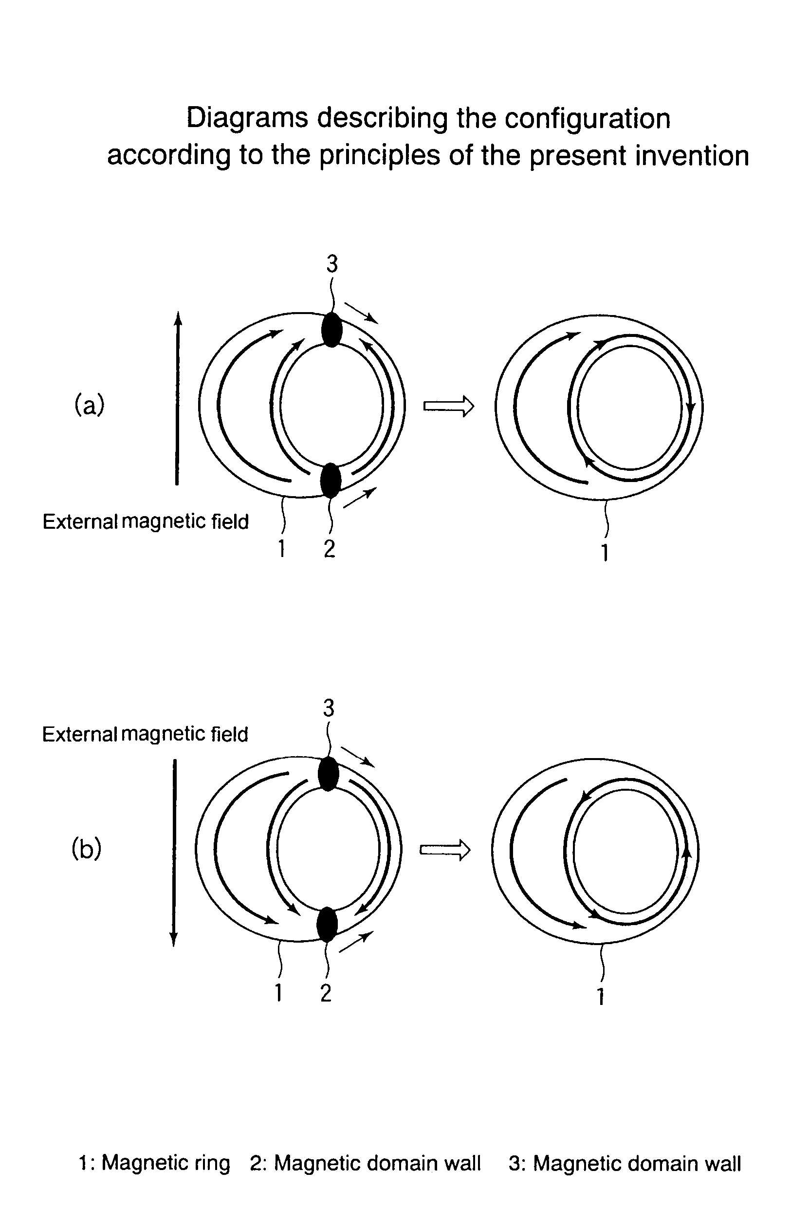
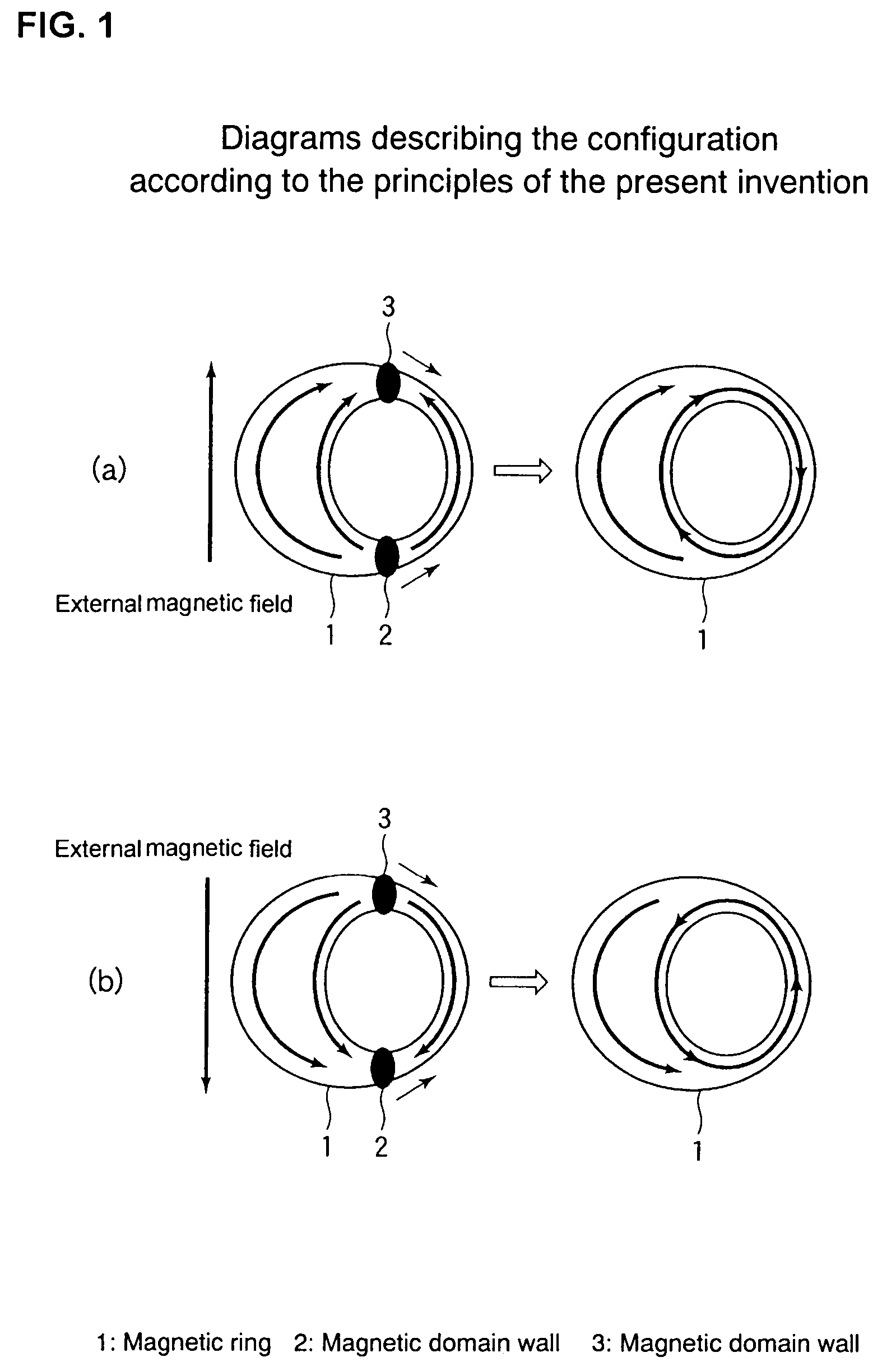
Magnetic ring unit and magnetic memory device
a magnetic memory and ring unit technology, applied in solid-state devices, knitting, instruments, etc., can solve the problems of inability to expect stable operation at room temperature, required antiferromagnetic patterns, etc., and achieve high recording density and high reliability
- Summary
- Abstract
- Description
- Claims
- Application Information
AI Technical Summary
Benefits of technology
Problems solved by technology
Method used
Image

Examples
first embodiment
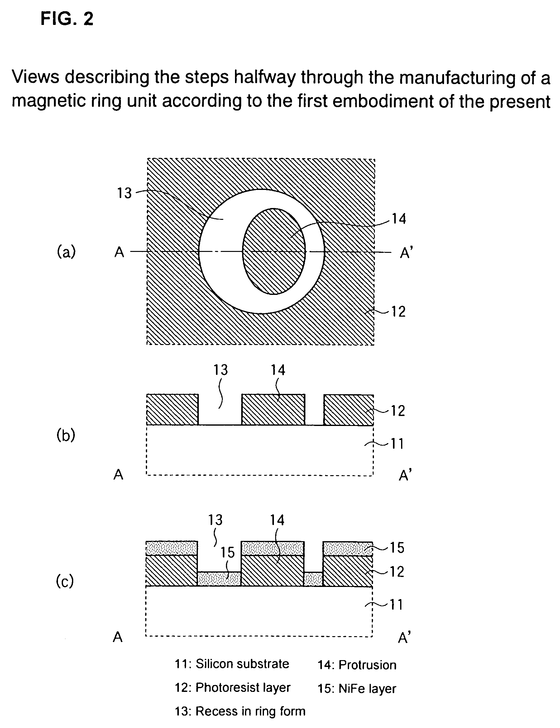
[0043]In reference to FIGS. 2(a) to 6 a magnetic ring unit according to the present invention is herein described. First, in reference to FIGS. 2(a) to 3(e), the manufacturing steps of the magnetic ring unit are described in the following.
[0044]See FIGS. 2(a) and 2(b).
[0045]FIG. 2(a) is a plan view and FIG. 2(b) is a schematic cross-sectional view along one-dotted chain line A–A′ of FIG. 2(a).
[0046]First, a photoresist layer 12 is applied to a silicon substrate 11 so as to have a thickness of, for example, 100 nm which is then exposed to light and developed so that a recess 13 in ring form is created.
[0047]In this case, the outer diameter of recess 13 in ring form is, for example, 500 nm while the plan form of an inner protrusion 14 is an ellipse having a major axis of 350 nm and a minor axis of 250 nm so that the recess is of an eccentric ring form wherein the center of the ellipse shifts from the center of the outer diameter by 50 nm in the direction of the minor axis.
[0048]See FI...
second embodiment
[0071]Next, in reference to FIGS. 7 to 9, an MRAM according to the present invention where a magnetic ring unit is used as a magnetic memory cell is described.
[0072]See FIG. 7.
[0073]FIG. 7 is a schematic cross-sectional view showing a main portion of an MRAM according to the second embodiment of the present invention wherein first a p-type well region 22 is formed in a predetermined region of an n-type silicon substrate 21 and n-type silicon substrate 21 is selectively oxidized so as to form an element isolation oxide film 23 and after that a gate electrode that becomes a sense line 25 for read-out is formed of WSi in an element formation region via a gate insulating film 24 so that this gate electrode is used as a mask for implanting ions such as As, or the like, and thereby, an n−-type LDD (lightly doped drain) region 26 is formed.
[0074]Subsequently, an SiO2 film or the like, is deposited on the entire surface and anisotropic etching is carried out so that sidewalls 27 are formed,...
PUM
 Abstract
Description
Claims
Application Information