
Boil-off gas processing system using electric heater

a technology of electric heater and processing system, which is applied in the direction of combustion control, non-pressure vessels, capillary burners, etc., can solve the problems of low temperature of boil-off gas, inability to process all of the produced boil-off gas by hydrogen storage alloy, and large amount of boil-off gas produced, so as to reduce the size of the system, reduce the capacity or energizing time of the electric heater, and use efficiently

Inactive Publication Date: 2006-03-07
HONDA MOTOR CO LTD
View PDF24 Cites 15 Cited by
  • Summary
  • Abstract
  • Description
  • Claims
  • Application Information

AI Technical Summary

Benefits of technology

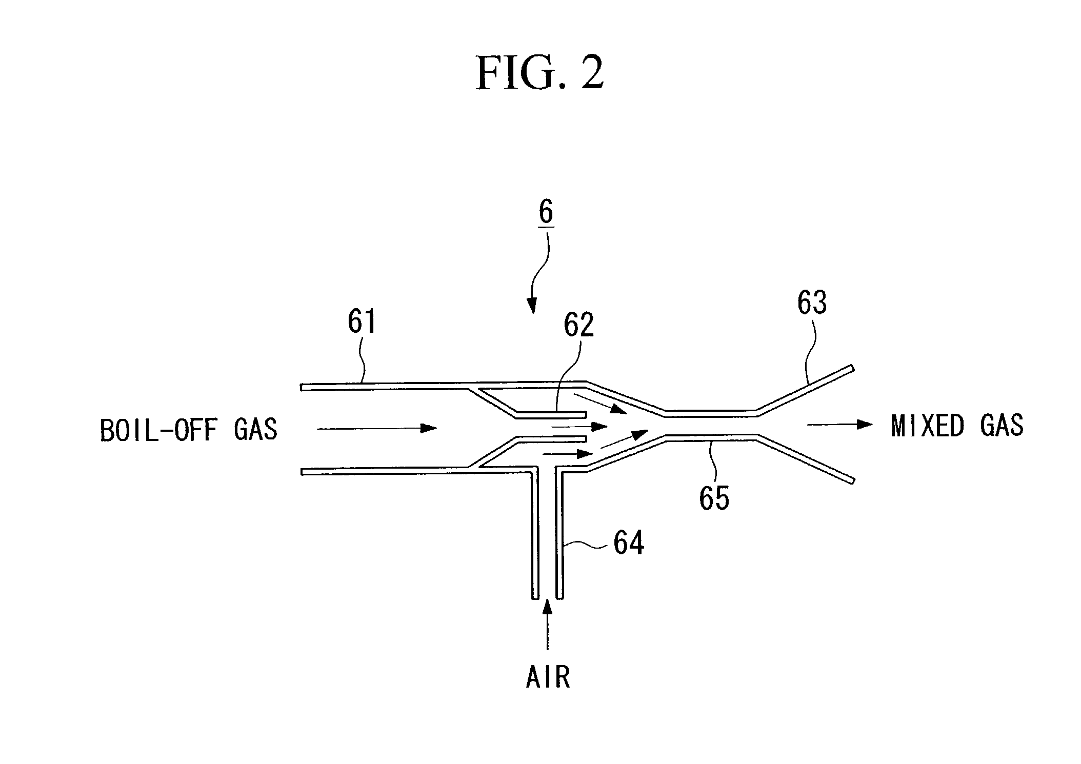
[0018]According to the above structure, the mixed gas, which was mixed by the mixing device, can be first heated by the electric heater and then be introduced to the catalyst in the catalytic combustor. Therefore, it is possible to quickly increasing the temperature of the catalyst to the activation temperature and to immediately activate the catalyst. Accordingly, the boil-off gas can be reliably burned and it is possible to prevent a pre-burned boil-off gas from being discharged.
[0023]According to this structure, the electric heater can be energized so as to heat the mixed gas only when the discharge valve is open and the boil-off gas is drawn into the catalytic combustor via the mixing device, that is, the electric heater cannot be energized while the discharge valve is closed and no boil-off gas is drawn into the catalytic combustor. Therefore, the power consumption of the electric heater can be minimized.
[0027]According to this structure, the electric heater can be energized only when the temperature of the catalytic combustor is lower than a predetermined temperature. Consequently, the electric heater is energized only when it is necessary, thereby reducing and minimizing the power consumption with respect to the electric heater.
[0028]As another typical example, the control section may start energizing of the electric heater before the boil-off gas included in the mixed gas is introduced into the catalytic combustor. In this case, the catalytic combustor can be preheated by energizing the electric heater before the boil-off gas is introduced into the catalytic combustor via the mixing device. Therefore, the catalyst can be activated before the introduction of the mixed gas, and the boil-off gas can be much more reliably burned.
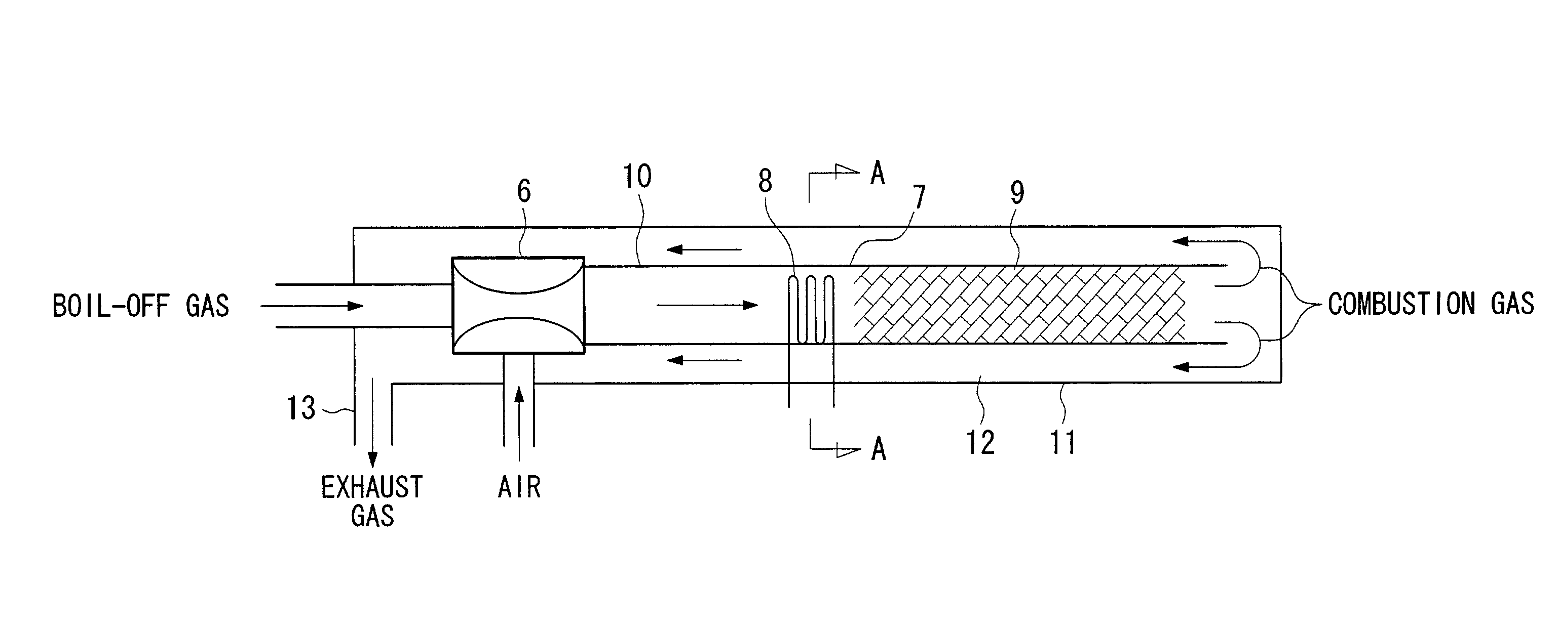
[0033]According to this structure, when the heating wire is energized, the catalyst adhered to the heating wire receives heat produced by the heating wire and is activated, so that the catalytic combustion of the mixed gas can be performed using the activated catalyst and the combustion gas produced by the catalytic combustion can heat and activate the catalyst of the downstream catalytic combustor. That is, the catalyst of the electric heater is first activated so as to perform the catalytic combustion of the mixed gas, and the downstream catalyst can be heated and activated by the combustion gas. Therefore, the boil-off gas can be immediately burned.
[0036]According to this structure, the catalytic combustor or the mixed gas before the introduction into the catalytic combustor can be heated by using waste heat of the combustion gas which passes through the combustion gas passage. Therefore, the combustion gas can assist the electric heater, so that the capacity or energizing time of the electric heater can be reduced. In addition, the combustion gas passage is provided in a manner such that a portion of the discharge passage, the portion being disposed from the catalytic combustor to the upstream side of the electric heater, is surrounded by the combustion gas passage. Therefore, all the heat of the combustion gas can be efficiently used and no additional heating device is necessary, so that the system size can be reduced.

Problems solved by technology

However, if a vehicle has not been used and driven for a long period, a considerable amount of boil-off gas is produced.
All of the produced boil-off gas may not be processed by a hydrogen storage alloy or the like.
However, as explained above, the temperature of boil-off gas is very low, and even if such boil-off gas is introduced into a catalytic combustor, the catalyst may not have an temperature necessary for activation.

Method used


Image

  • Boil-off gas processing system using electric heater
  • Boil-off gas processing system using electric heater
  • Boil-off gas processing system using electric heater

Examples


Embodiment Construction

[0045]Hereinafter, embodiments of the boil-off gas processing system according to the present invention will be explained with reference to the drawings (FIGS. 1 to 8).

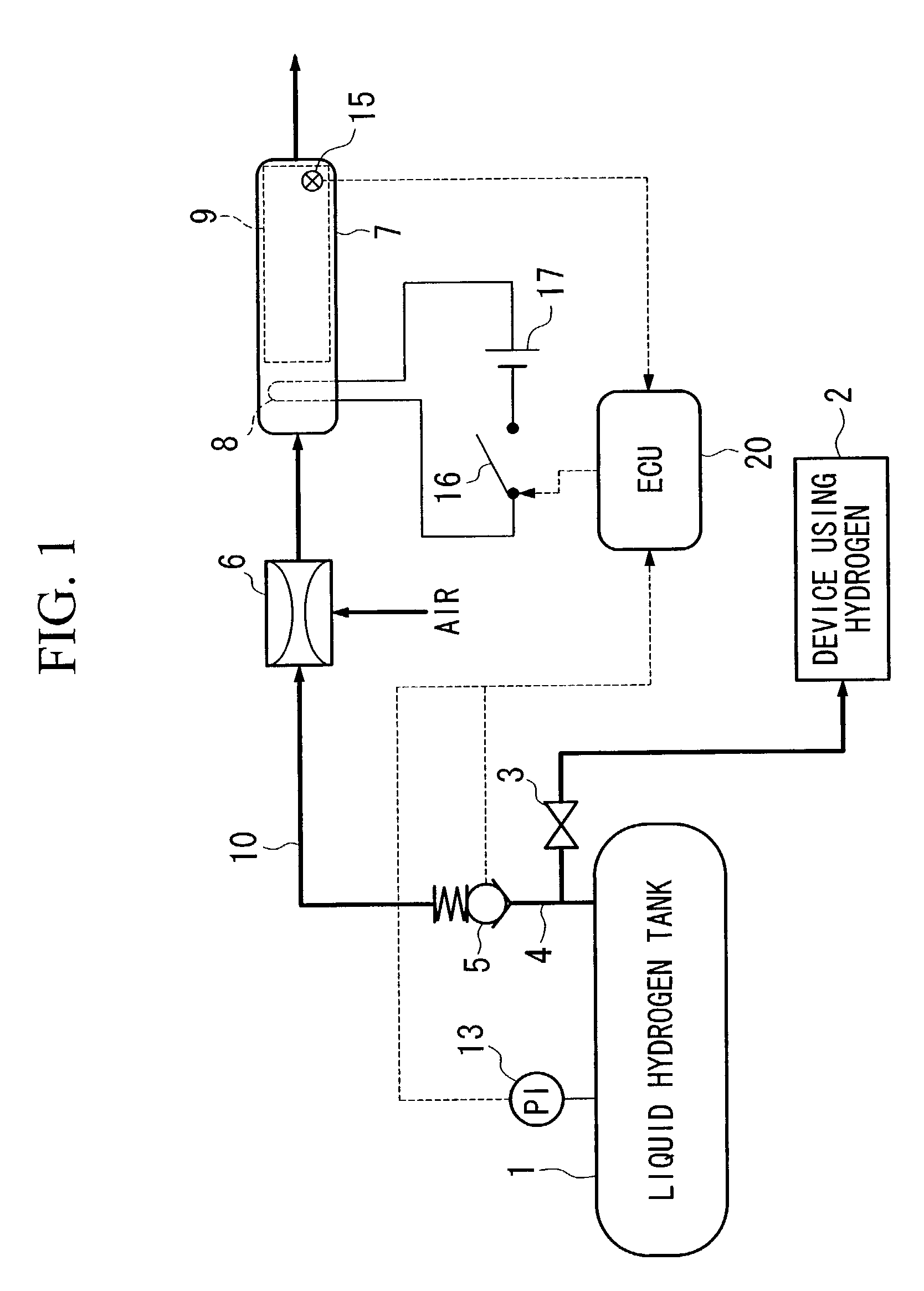
[0046]The boil-off gas processing system is built into a vehicle, which is driven by a device using hydrogen, such as a hydrogen fueled engine or a fuel cell, that is, into a hydrogen fueled vehicle.

[0047]FIG. 1 is a diagram showing the general structure of the boil-off gas processing system. Liquid hydrogen is stored in a liquid hydrogen tank 1, and hydrogen gas produced by vaporization of this liquid hydrogen is supplied as a fuel via a control valve 3 to a device 2 using hydrogen (such as a fuel cell or the like) while the device 2 is operated.

[0048]When the device 2 (using hydrogen) is stopped, if the temperature of the liquid hydrogen tank 1 is increased by external heat, vaporized hydrogen increases in the tank 1, thereby increasing the pressure in the tank 1. When the pressure in the liquid hydrogen tank 1 reac...


PUM


Abstract

A boil-off gas processing system for reliably burning a boil-off gas. The system processes a boil-off gas produced from a liquid hydrogen tank which is built in a hydrogen fueled vehicle. The system includes a mixing device for introducing air into a discharge passage through which the boil-off gas from the liquid hydrogen tank passes and for mixing the air and the boil-off gas and outputting a mixed gas; a catalytic combustor for burning the mixed gas which was mixed by the mixing device, the catalytic combustor having an inlet through which the mixed gas is introduced and an outlet for discharging combustion gas; an electric heater provided at the inlet side of the catalytic combustor; and a control section for controlling energizing of the electric heater.

Description

BACKGROUND OF THE INVENTION[0001]1. Field of the Invention[0002]The present invention relates to a boil-off gas processing system for burning and discharging a boil-off gas produced from liquid hydrogen, and in particular, to a system built into a vehicle, where the vehicle is driven by a device using hydrogen, such as a hydrogen fueled engine or a fuel cell.[0003]2. Description of the Related Art[0004]In an example structure of conventional fuel cells, a solid polymer electrolyte membrane is placed between an anode and a cathode, and a hydrogen gas functioning as a fuel gas is supplied to the anode while air or the like which functions as an oxidizing gas is supplied to the cathode. The chemical energy produced by the oxidation reduction reaction of these gases is directly extracted as electrical energy. Such a solid polymer electrolyte membrane fuel cell has a high energy-output efficiency and is environmentally clean; thus, this type of the fuel cell is often employed in motor ve...

Claims


Application Information

Patent Timeline
IPC IPC(8): F23D21/00F17C13/02F17C9/04F23N5/02F23D99/00B01D53/86F23C13/00F23G7/06F23G7/07H01M8/00H01M8/04H01M8/06H01M8/10
CPCF23C13/00F23C13/02F23G7/07H01M8/0606F23C2900/9901Y02E60/50H01M8/04201H01M8/0662Y02E60/321F23N2037/12F23N2237/12Y02E60/32
Inventor SHIMADA, TOSHIAKIKURIIWA, TAKAHIRONUIYA, YOSHIO
Owner HONDA MOTOR CO LTD
Learn More