
Starter solenoid switch with highly reliable contacts

a solenoid switch and high-reliability technology, which is applied in the direction of engine starters, machines/engines, relays, etc., can solve the problems of limited electric current supplied to the starter motor, difficulty in cranking the engine, and easy wear of the pinion gear and the ring gear

Active Publication Date: 2006-03-07
DENSO CORP
View PDF9 Cites 7 Cited by
  • Summary
  • Abstract
  • Description
  • Claims
  • Application Information

AI Technical Summary

Benefits of technology

[0016]The present invention has been made in view of the above-mentioned problem; it is, therefore, a primary object of the present invention to provide a starter solenoid switch with an auxiliary contact portion that is made of carbon materials and has an improved structure ensuring high reliability of the auxiliary contact portion.

Problems solved by technology

When the starter of an automobile equipped with an idle stop system is designed to crank the engine by bringing a pinion gear thereof into mesh with a ring gear of the engine, the pinion gear and the ring gear may be easily worn down due to the frequent operation of the starter.
As a result, the pinion gear of the starter cannot be smoothly brought in mesh with the ring gear of the engine, thus resulting in a difficulty in cranking the engine.
Moreover, the fixed contact of the auxiliary contact portion is made of a carbon material that has a high electric resistivity, so that only limited electric current is supplied to the starter motor when only the auxiliary contact portion is closed in the first stage.
However, since carbon has a high electric resistivity, when electric current passes through the auxiliary contact portion, heat may be considerably generated by the fixed contact of the auxiliary contact portion that is made of the carbon material, thereby causing thermal expansion and shrinkage of the metal holder that is connected with the fixed contact.
As a result, cracks may be generated in the contacting area between the metal holder and the fixed contact of the auxiliary contact portion due to the difference in coefficient of thermal expansion therebetween, thereby causing a failure of the electrical connection between the battery and the starter motor.
However, the difference in coefficient of thermal expansion between the fixed contact of the auxiliary contact portion that is made of the carbon material and the copper twisted wire would still cause cracks in the contacting area therebetween, thereby causing a failure of the electrical connection.
As a result, a high level of heat may be generated at those contact points due to the high electric resistively of the fixed contact made of the carbon material, thereby causing carbon particles to be separated from the contact surface at those points.

Method used


Image

  • Starter solenoid switch with highly reliable contacts
  • Starter solenoid switch with highly reliable contacts
  • Starter solenoid switch with highly reliable contacts

Examples


first embodiment

[First Embodiment]

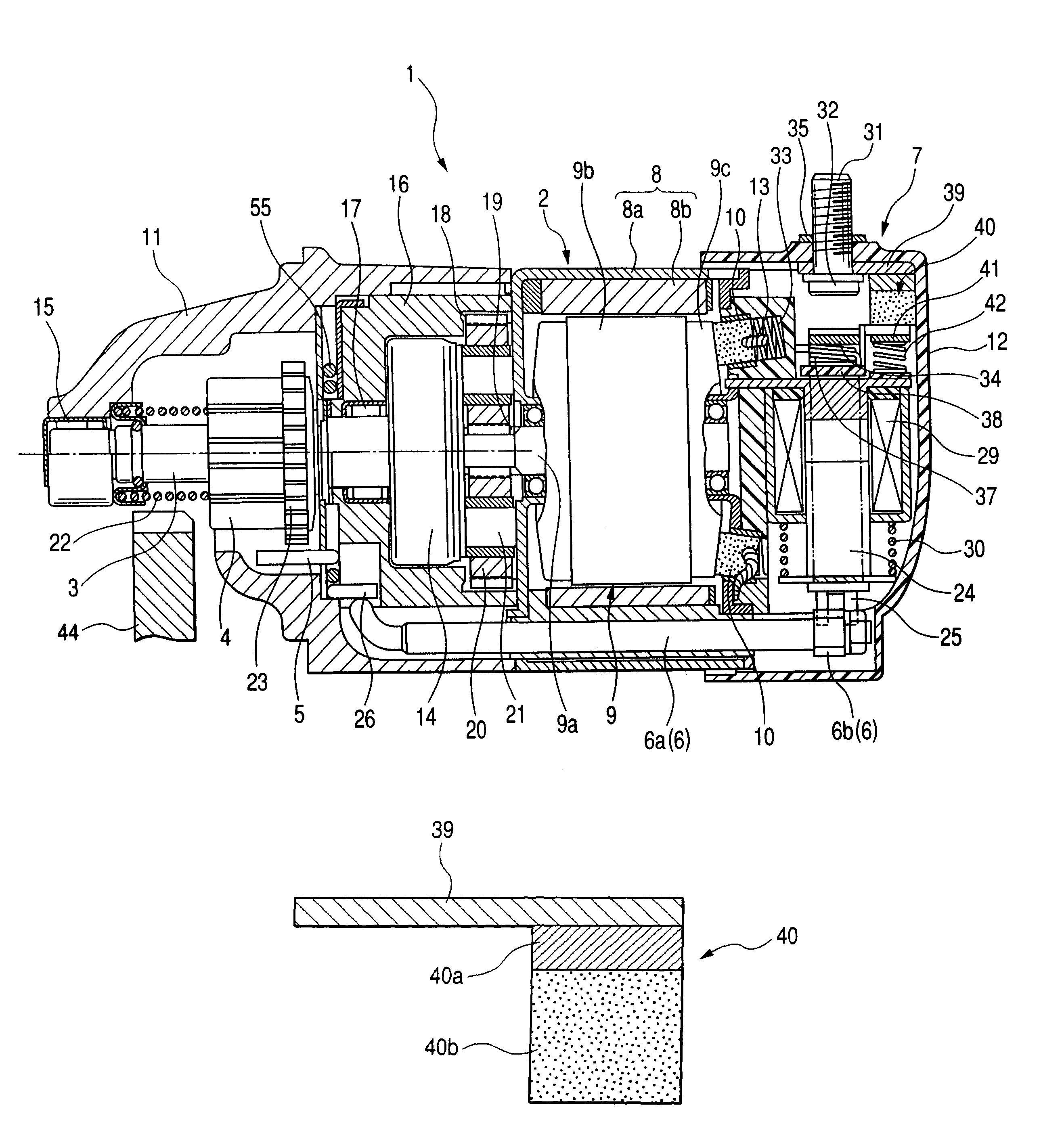
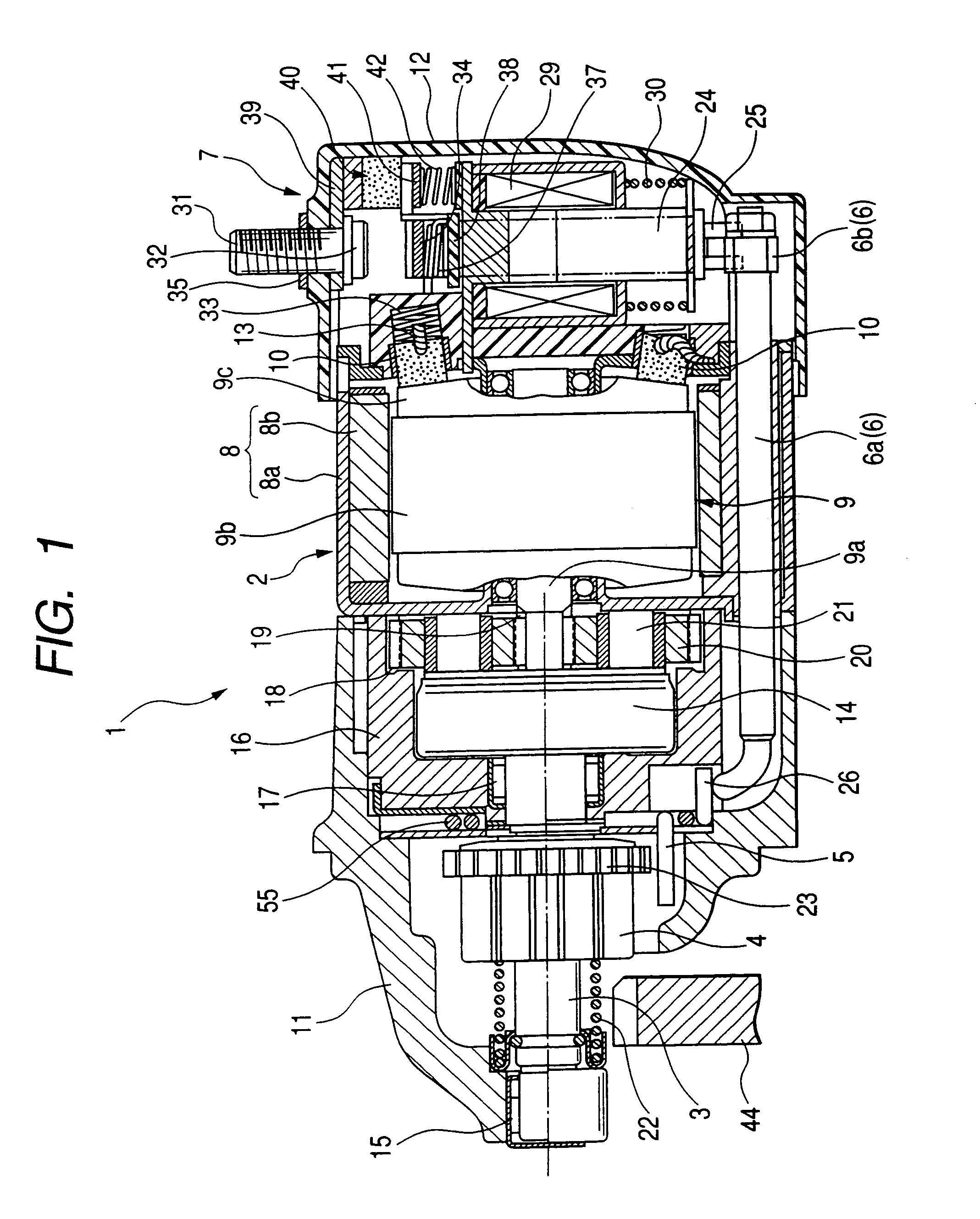
[0047]FIG. 1 shows an overall structure of a starter 1 that includes a starter solenoid switch 7 according to the first embodiment of the invention.

[0048]As shown in FIG. 1, the starter 1 includes a starter motor 2, an output shaft 3 driven by the starter motor 2, a pinion gear 4 mounted on the output shaft 3, a rotation restriction member 5 that restricts rotation of the pinion gear 4 before start up of the starter motor 2, and the solenoid switch 7 that makes and breaks an electrical connection for supplying electric power to the starter motor 2 and drives the rotation restriction member 5 via a connecting member 6.

[0049]The starter motor 2 is a DC motor including a magnetic field system 8 that creates a magnetic flux, an armature 9 with a commutator, and brush 10 that is in slidable contact with the commutator.

[0050]The magnetic field system 8 includes a yoke 8a for forming a magnetic circuit and a plurality of permanent magnets 8b disposed on inner periphery of...

second embodiment

[Second Embodiment]

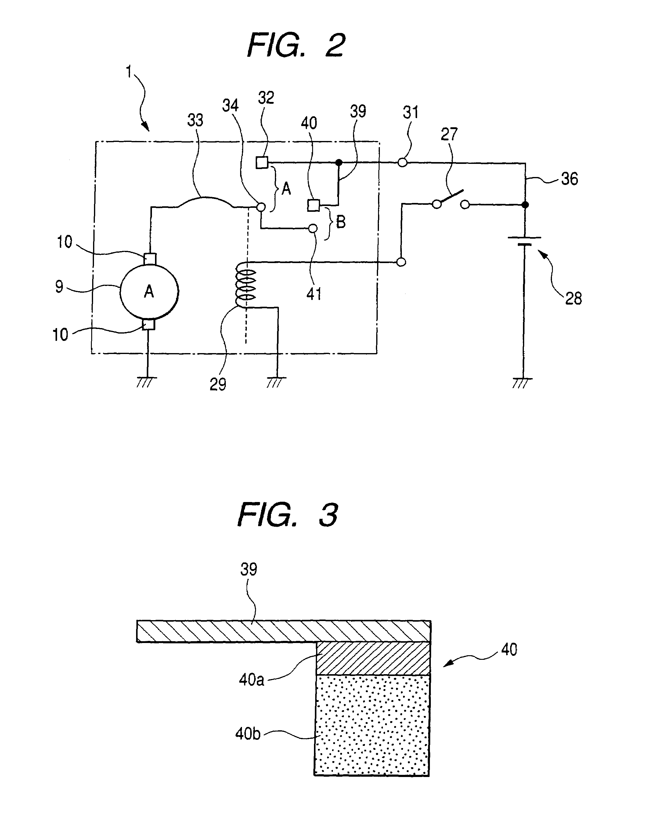
[0093]FIG. 4 shows a second fixed contact 40 of a starter solenoid switch according to the second embodiment of the present invention.

[0094]The starter solenoid switch of the present embodiment is almost identical to that of the previous embodiment.

[0095]However, in this embodiment, the conductive metal plate 39 is partially embedded in the low-resistance portion 40a of the second fixed contact 40 and integrally formed with the low-resistance portion 40a; in the previous embodiment, it is connected to the low-resistance portion 40 abutting the end of the low-resistance portion 40.

third embodiment

[Third Embodiment]

[0096]FIG. 5 shows a second fixed contact 40 of a starter solenoid switch according to the third embodiment of the present invention.

[0097]The starter solenoid switch of the present embodiment is almost identical to those of the previous embodiments.

[0098]However, in this embodiment, an electrically conductive lead 43 is used, instead of the conductive metal plate 39 in the previous embodiments, to electrically connect the second fixed contact 40 with the external terminal 31 described previously. The electrically conductive lead 43 is partially embedded in the low-resistance portion 40a of the second fixed contact 40 and integrally formed with the low-resistance portion 40a.

[0099]The electrically conductive lead 43 is made, for example, of copper twisted wire 43. Since the electrically conductive lead 43 has flexibility, the use thereof provides a flexibility in arranging the second fixed contact 40 in the starter solenoid switch.


PUM


Abstract

A starter solenoid switch according to the present invention includes a first and a second set of contacts that are disposed between a battery and a starter motor in parallel with each other. The first and the second sets of contacts are so configured that the second set of contacts is closed to supply a lighter electric current to the starter motor before the first set of contacts is closed to supply a heavier electric current to the same. The second set of contacts is composed of a second fixed contact and a second movable contact, one of which includes a low-resistance portion at one end thereof and a high-resistance portion that contains more carbon than the low-resistance portion. The low-resistance and the high-resistance portions are serially disposed along a conducting path of electric current from the battery to the starter motor, thereby ensuring reliability of the starter solenoid switch.

Description

CROSS-REFERENCE TO RELATED APPLICATION[0001]This application claims priority from Japanese Patent Application No. 2004-44984, filed on Feb. 20, 2004, the content of which is hereby incorporated by reference into this application.BACKGROUND OF THE INVENTION[0002]1. Technical Field of the Invention[0003]The present invention relates generally to a starter solenoid switch for supplying electric power from a battery to a starter motor in two stages. More particularly, the invention relates to an improved structure of a set of contacts of the starter solenoid switch, which makes and breaks an electrical connection between the battery and the starter motor.[0004]2. Description of the Related Art[0005]In recent years, the number of automobiles, which are equipped with an idle stop system, has increased to meet a demand of improving fuel economy and reducing exhaust gases.[0006]An idle stop system is generally employed to automatically stop the engine when the automobile is stopped for, by ...

Claims


Application Information

Patent Timeline
Patent Type & Authority Patents(United States)
IPC IPC(8): H01H67/02F02N15/06F02N11/00H01H1/04H01H51/06
CPCF02N15/067H01H51/065H01H50/543F02N2300/102
Inventor NIIMI, MASAMISHIGA, TSUTOMUKURASAWA, TADAHIRO
Owner DENSO CORP
Learn More