Effective proximity effect correction methodology
- Summary
- Abstract
- Description
- Claims
- Application Information
AI Technical Summary
Benefits of technology
Problems solved by technology
Method used
Image


Examples
Embodiment Construction
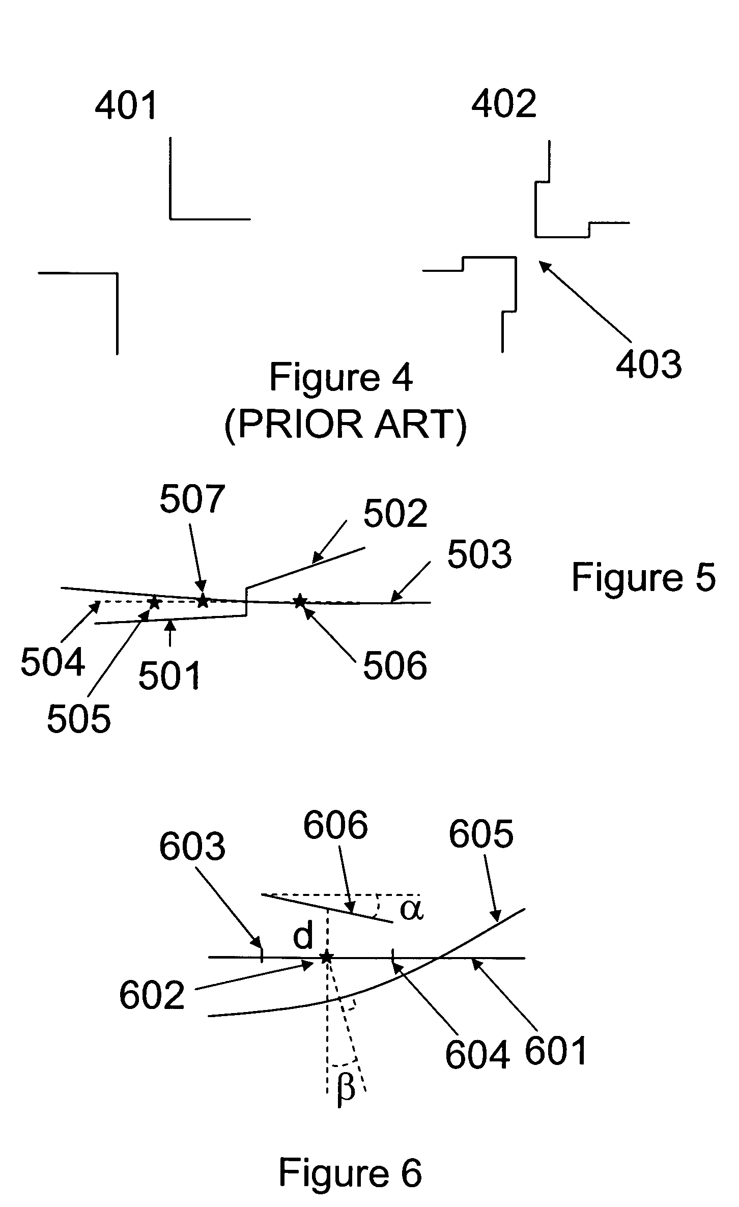
[0050]FIG. 5 illustrates how a better extrapolation of the correction can be achieved by changing the angle of the segments. The target layout and original placement of the segments is represented by the line 504. 501 and 502 represent the position of the segments after correction. It should be noted that the segments have been shifted as well as rotated from their original position along line 504. The evaluation points for the segments 501 and 502 are respectively 505 and 506. Line 503 indicates the position of the image on the wafer when the corrected data is used. Compared to FIG. 3 (same target as FIG. 3), a better correction was achieved thanks to the rotation of the segments for a point 507 in-between the evaluation points 505 and 506.
[0051]FIG. 6 illustrates one method used to calculate the shift and rotation of the segments. Line 601 represents the original layout as well as the target wafer image. An evaluation point 602 is placed on line 601 with two dissection points 603 ...
PUM
 Abstract
Description
Claims
Application Information
 - Generate Ideas
- Intellectual Property
- Life Sciences
- Materials
- Tech Scout
- Unparalleled Data Quality
- Higher Quality Content
- 60% Fewer Hallucinations
Browse by: Latest US Patents, China's latest patents, Technical Efficacy Thesaurus, Application Domain, Technology Topic, Popular Technical Reports.
© 2025 PatSnap. All rights reserved.Legal|Privacy policy|Modern Slavery Act Transparency Statement|Sitemap|About US| Contact US: help@patsnap.com