Washing machine with vector control for drive motor

a technology of drive motor and wash machine, which is applied in the direction of electric generator control, dynamo-electric converter control, dynamo-electric gear control, etc., can solve the problems of increasing the adverse effect of output current waveform, increasing the risk of difference, and increasing control instability, so as to improve the responsibility, reduce noise and vibration or oscillation, and achieve the torque required to achieve a predetermined speed. , the effect of easy to obtain

Inactive Publication Date: 2006-03-28
TOSHIBA LIFESTYLE PROD & SERVICES CORP
View PDF7 Cites 30 Cited by
  • Summary
  • Abstract
  • Description
  • Claims
  • Application Information

AI Technical Summary

Benefits of technology

[0012]Since the torque controller performs the vector control, it can directly control the motor torque while the motor torque is in proportion to a q-axis current. Accordingly, this control manner can improve the responsibility as compared with the conventional motor control manners, and noise and vibration or oscillation can be reduced.
[0013]In a preferred form, the washing machine further comprises a speed controller provided at a stage previous to the torque controller for performing a PI control for a motor speed on the basis of a speed command and a speed of the motor obtained from the current detected by the current detector. In this preferred f...

Problems solved by technology

However, the developed torque is not proportional to the voltage when the control is performed by increasing or decreasing the applied voltage as described above.
As a result, a difference is likely to occur between the target speed command ωref and the detected speed ω, whereupon the control becomes unstable.
Accordingly, an adverse effect on the output current waveform becomes larger as ...

Method used


Image

  • Washing machine with vector control for drive motor
  • Washing machine with vector control for drive motor
  • Washing machine with vector control for drive motor

Examples


first embodiment

[0038]Several embodiments of the invention will be described with reference to the accompanying drawings. The invention is applied to a vertical axis type automatic washing machine in the embodiments. Identical or similar parts are labeled by the same reference symbols throughout the embodiments. FIGS. 1 to 12 illustrate the invention. Referring to FIG. 3, an overall construction of the automatic washing machine 11 is shown. The washing machine 11 comprises a generally rectangular box-shaped outer cabinet 12 and a stationary water-receiving tub 13 elastically supported by four elastic suspension mechanisms 14 in the cabinet 12. Each suspension mechanism 14 includes a suspension rod 14a having an upper end mounted on an upper portion of the cabinet 12 and a coil spring 14b mounted on a lower end of the suspension rod 14a. An amount of vibration or oscillation produced during a washing operation can be prevented from transmission to the cabinet 12.

[0039]A rotating tub 15 serving as a ...

second embodiment

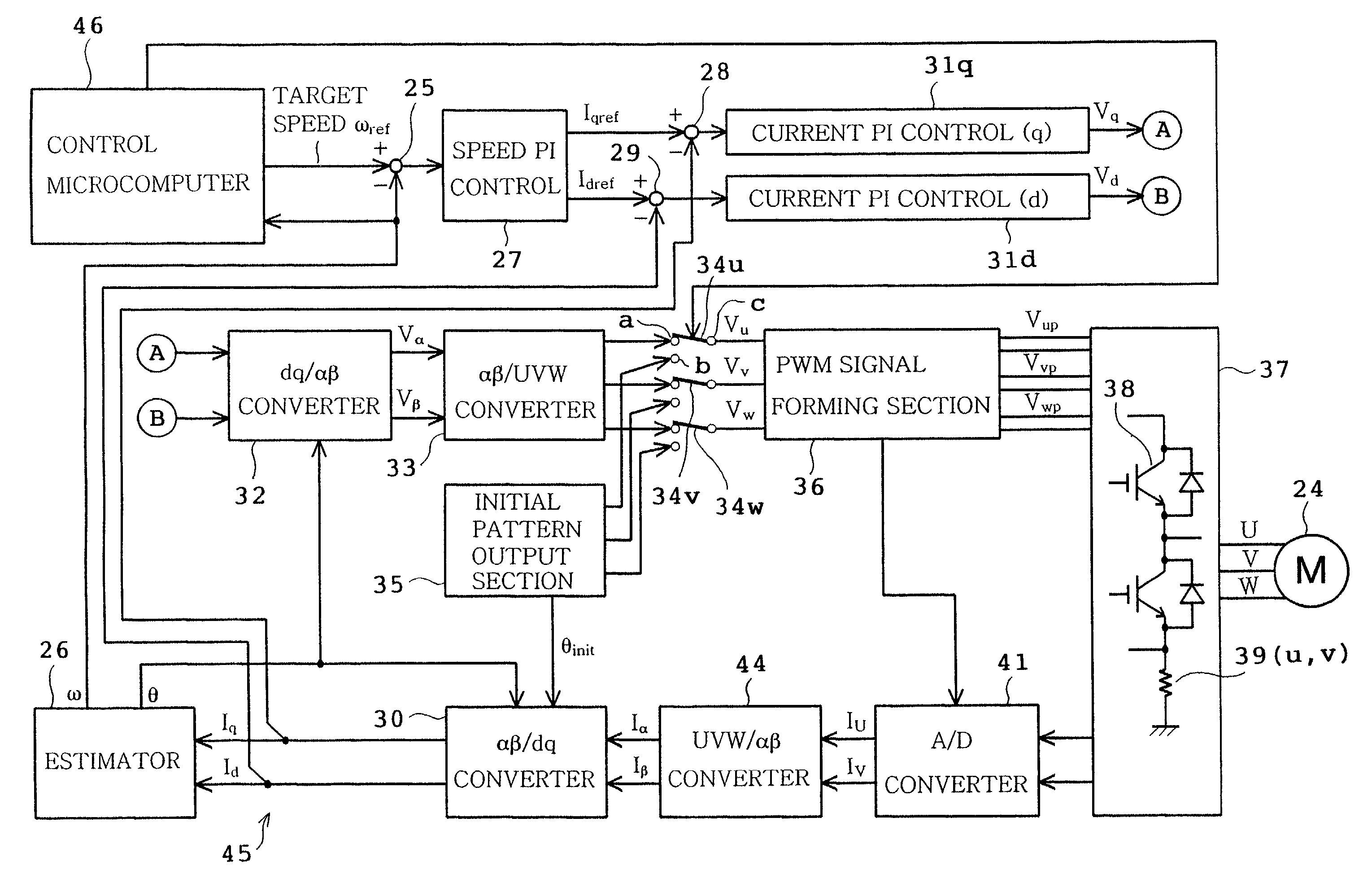
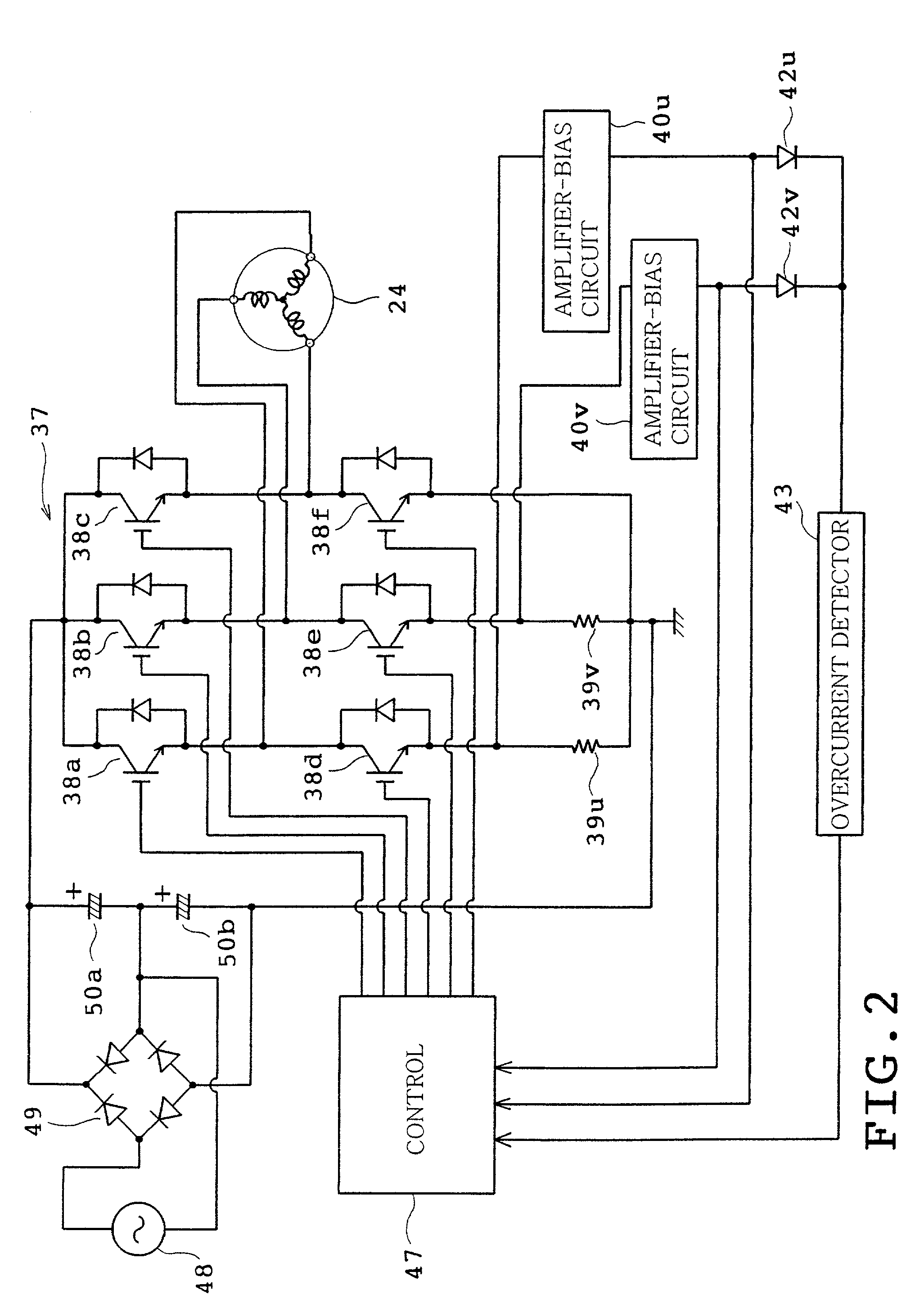
[0072]In the arrangement of the second embodiment, the A / D converters 41A1 and 41A2 detect the currents with respect to two of the three phases in which the phase voltages do not show the maximum level. Accordingly, in the section in which the phase voltage shows the maximum level, the duty of the PWM signal can be set at 100% without turn-on of the lower arm side IGBT 38. Consequently, the efficiency of the motor 24 can be improved. For example, a reduction of about 15 W can be achieved in the power consumption when the drive voltage of the inverter circuit 38 is about 280 V. The foregoing can be applied to a case of the sinusoidal wave energization by way of the three-phase modulated wave.

[0073]FIG. 17 illustrates a third embodiment of the invention. Only the difference of the third embodiment from the first embodiment will be described. In the third embodiment, two series connected shunt resistors are connected to the lower arm side of the inverter circuit 37 for each phase. More...

third embodiment

[0075]In the third embodiment as described above, the control 47B switches the resistance value of the detecting resistor according to the amount of current flowing into the motor windings. Consequently, the current can precisely be detected even in the washing machine in which the load variation is usually large.

[0076]FIGS. 18 to 21 illustrate a fourth embodiment of the invention. The shunt resistors 39u, 39v and 49w are eliminated in the fourth embodiment. Two shunt resistors 51v and 51w are interposed between the output terminals 37v and 37w of the inverter circuit 37 and motor windings 24v and 24w respectively. Two current detecting ICs 52v and 52w have input terminals connected between both ends of the resistors 51v and 51w respectively. For example, product IR2717 manufactured by International Rectifier may be used as the current detecting ICs 52v and 52w. The current detecting ICs 52v and 52w deliver PWM signals according to terminal voltages of the resistors 51v and 51w to t...


PUM


Abstract

A washing machine includes an electric motor developing torque used for wash, rinse and dehydration operations, a current detector detecting current flowing into the motor, and a torque controller performing a vector control for the motor on the basis of the current detected by the current detector so that the torque developed by the motor is optimum for at least each of the wash and dehydration operations.

Description

BACKGROUND OF THE INVENTION[0001]1. Field of the Invention[0002]This invention relates to a washing machine provided with a control device executing torque control for an electric motor developing torque used to carry out wash, rinse and dehydration operations.[0003]2. Description of Related Art[0004]Automatic washing machines have conventionally been provided which comprise a brushless DC motor driving an agitator (or pulsator) and a rotating tub in a wash step and only the rotating tub in a rinse step and a dehydration step. An inverter circuit is provided for driving the brushless DC motor in many types of the above-mentioned washing machines. Voltage applied to the motor is increased or decreased so that torque developed by the motor is controlled according to a driving condition of the motor.[0005]FIG. 22 shows an example of control system for a three-phase drive motor of the aforementioned conventional automatic washing machine. The control system is composed of a microcompute...

Claims


Application Information

Patent Timeline
IPC IPC(8): D06F33/04D06F33/02H02P6/08D06F35/00D06F37/20D06F37/30H02P21/00H02P21/06
CPCD06F37/203D06F37/304H02P21/0035H02P21/06Y02B40/52D06F2202/12H02P21/22Y02B40/00D06F33/48D06F2103/24D06F2105/48D06F2103/46
Inventor HOSOITO, TSUYOSHITANAKA, TOSHIMASAOKAZAKI, YOJIITO, MICHIAKIKAWABATA, SHINICHIRONAGAI, KAZUNOBUISONO, FUTOSHI
Owner TOSHIBA LIFESTYLE PROD & SERVICES CORP
Why Eureka
Try Eureka