Tear film osmometry

a technology of osmolarity and tear film, which is applied in the field of measuring the osmolarity of tear film, can solve the problems of cornea ulceration, intractable desiccation, severe impact on the eye, etc., and achieves accurate osmolarity measurement, reliable osmolarity measurement, and quick and easy obtained

Active Publication Date: 2006-03-28
RGT UNIV OF CALIFORNIA
View PDF28 Cites 53 Cited by
  • Summary
  • Abstract
  • Description
  • Claims
  • Application Information

AI Technical Summary

Benefits of technology

[0013]Osmolarity measurement of a sample fluid, such as a tear film, is achieved by depositing an aliquot volume of the sample fluid on a microchip having a substrate and a sample region of the substrate, wherein the volume of the sample fluid operatively covers a sufficient portion of the sample region such that energy imparted to the sample fluid is detected from the sample region to produce an output signal that indicates osmolarity of the sample fluid. Thus, an osmolarity measurement of the sample fluid can be obtained from the detected energy of the sample volume. The aliquot-sized samp

Problems solved by technology

Disruption, deficiency, or absence of the tear film can severely impact the eye.
If unmanaged with artificial tear substitutes or tear film conservation therapy, these disorders can lead to intractable desiccation of the corneal epithelium, ulceration and perforation of the cornea, an increased incidence of infectious disease, and ultimately pronounced visual impairment and blindness.
However, these ex vivo measurements are often plagued by many difficulties.
Any dilution of the tear film invalidates the diagnostic ability of an osmolarity test for dry eye, and therefore make currently available ex vivo methods prohibitive in a clinical setting.
Because of the induction of reflex tearing and the large volume requirements for existing vapor pressure osmometers, they are currently impractical for determination of dry eye.
The Clifton Nanoliter Osmometer (available from Clifton Technical Physics of Hart

Method used


Image

  • Tear film osmometry
  • Tear film osmometry
  • Tear film osmometry

Examples


Embodiment Construction

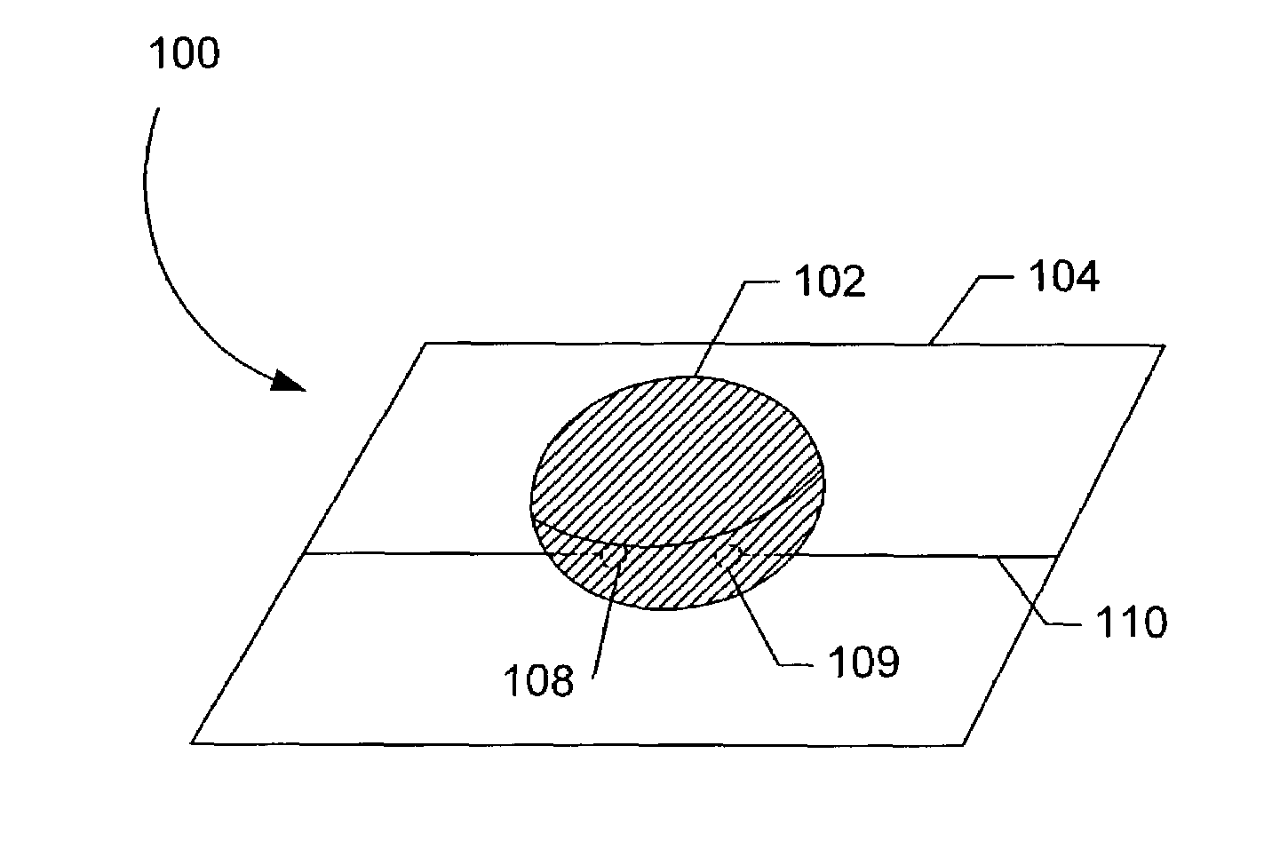
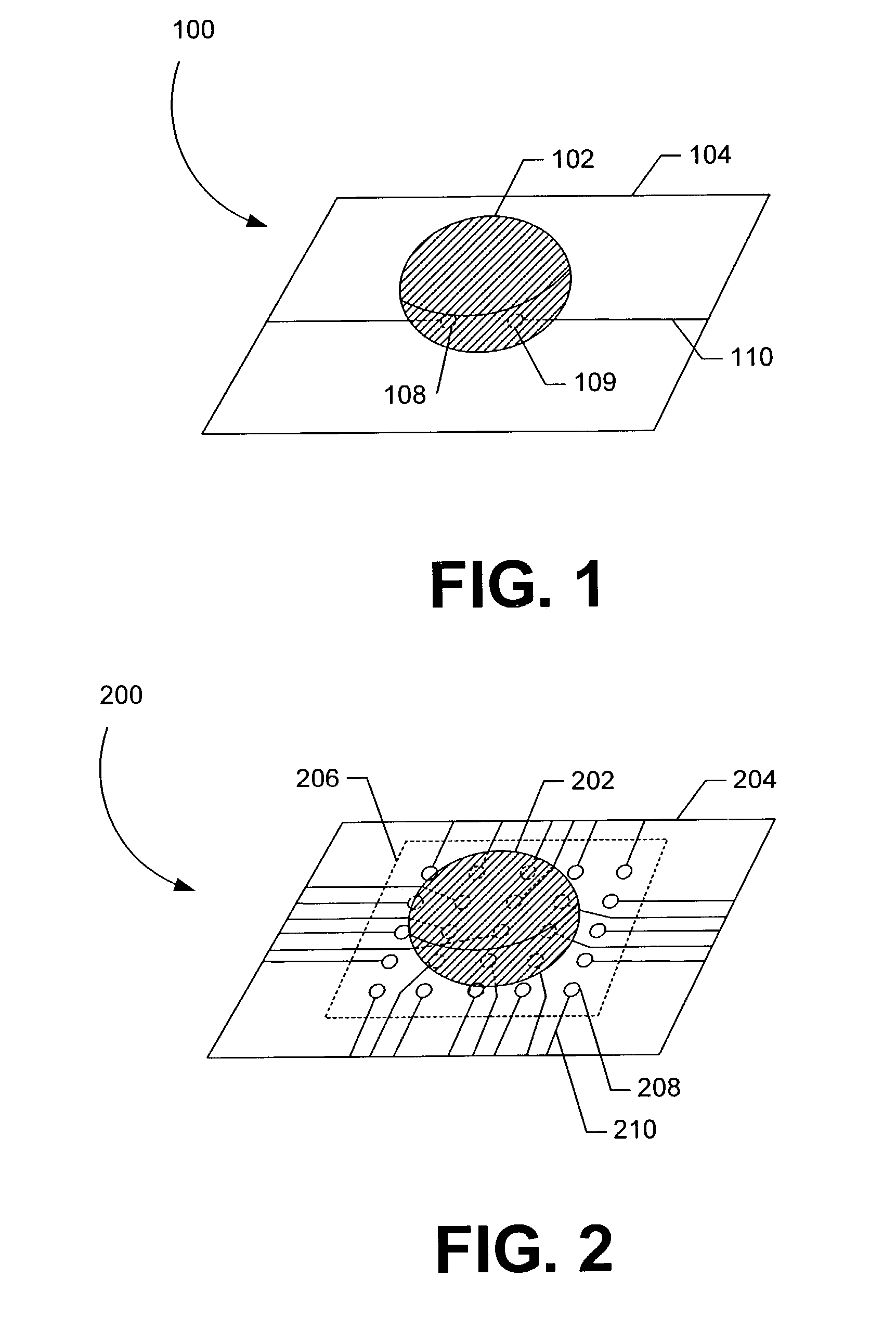
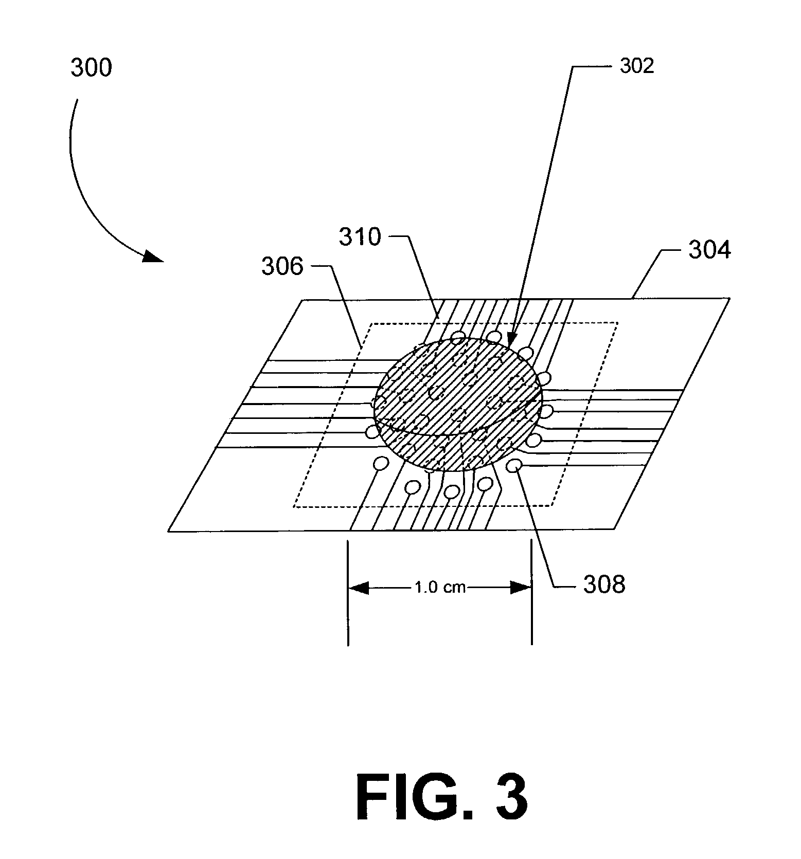
[0030]Exemplary embodiments are described for measuring the osmolarity of an aliquot volume of a sample fluid (e.g., tear film, sweat, blood, or other fluids). The exemplary embodiments are configured to be relatively fast, non-invasive, inexpensive, and easy to use, with minimal risk of injury to the patient. Accurate measurements can be provided with as little as nanoliter volumes of a sample fluid. For example, a measuring device configured in accordance with the invention enables osmolarity measurement with no more than 20 μL of sample fluid, and typically much smaller volumes can be successfully measured. In one embodiment described further below, osmolarity measurement accuracy is not compromised by variations in the volume of sample fluid collected, so that osmolarity measurement is substantially independent of collected volume. The sample fluid can include tear film, sweat, blood, or other bodily fluids. It should be noted, however, that sample fluid can comprise other fluid...


PUM


Abstract

Osmolarity measurement of a sample fluid, such as tear film, is achieved by depositing an aliquot-sized sample on a sample receiving substrate. The sample fluid is placed on a sample region of the substrate. Energy is imparted to the sample fluid and energy properties of the fluid can be detected to produce a sample fluid reading that indicates osmolarity of the sample fluid. An aliquot-sized volume can comprise, for example, a volume of no more than 20 microliters (μL). The aliquot-sized sample volume can be quickly and easily obtained, even from dry eye sufferers. The imparted energy can comprise electrical, optical or thermal energy. In the case of electrical energy, the energy property of the sample fluid can comprise electrical conductivity. In the case of optical energy, the energy property can comprise fluorescence. In the case of thermal energy, the measured property can be the freezing point of the sample fluid. The substrate can be packaged into a chip, such as by using semiconductor fabrication techniques. An ex vivo osmolarity sensor system that uses the chip can detect energy from the sample region and can provide an accurate osmolarity measurement without user intervention.

Description

REFERENCE TO PRIORITY DOCUMENT[0001]This application claims the benefit of priority of co-pending U.S. Provisional Patent Application Ser. No. 60 / 401,432 entitled “Volume Independent Tear Film Osmometer”, by Benjamin D. Sullivan, filed Aug. 6, 2002. Priority of the filing date of Aug. 6, 2002 is hereby claimed, and the disclosure of the Provisional Patent Application is hereby incorporated by reference.BACKGROUND[0002]1. Field[0003]The present invention relates generally to measuring the osmotic pressure of fluids and, more particularly, to measuring the osmolarity of tear film.[0004]2. Description of the Related Art[0005]Tears fulfill an essential role in maintaining ocular surface integrity, protecting against microbial challenge, and preserving visual acuity. These functions, in turn, are critically dependent upon the composition and stability of the tear film structure, which includes an underlying mucin foundation, a middle aqueous component, and an overlying lipid layer. Disru...

Claims


Application Information

Patent Timeline
IPC IPC(8): G01N13/04A61B5/00G01N33/483G01N27/02G01N27/06G01N33/50G01N37/00
CPCG01N13/04
Inventor SULLIVAN, BENJAMIN D.
Owner RGT UNIV OF CALIFORNIA
Why Eureka
Try Eureka