Systems and methods for ion beam focusing

a technology of ion beams and focusing apparatuses, applied in the direction of magnetic discharge control, separation process, instruments, etc., can solve the problems of low energy ion beams b>24/b> being particularly susceptible to beam divergence or beam blowup, and achieve the effect of reducing the risk of beam blowup or other beam profile distortion, improving the control of incident beam uniformity, and controlling the implantation uniformity

Active Publication Date: 2006-03-28
AXCELIS TECHNOLOGIES
View PDF13 Cites 22 Cited by
  • Summary
  • Abstract
  • Description
  • Claims
  • Application Information

AI Technical Summary

Benefits of technology

[0008]The invention provides systems and methods for focusing scanned ion beams in ion implanters that may be employed to mitigate beam blowup or other beam profile distortion as the scanned ion beam travels between a beam scanner and a workpiece location. The invention may thus advantageously provide improved control of incident beam uniformity, and hence help to control the implantation uniformity of semiconductor wafers, display panels, or other workpieces. The invention provides beam focusing fields along a portion of a scan plane of a scanned ion beam, with a time varying focusing field center, where the center is temporally translated along the scan direction to be generally spatially coincident with the time-varying position of the scanned ion beam along the scan direction. In this manner, the scanned beam may be advantageously focused prior to incidence on the workpiece surface, even where post-collimation deceleration has increased the tendency of the beam to blow up or otherwise deviate from a desired beam profile.
[0009]One aspect of the invention relates to an ion implantation system or ion implanter, comprising an ion source that produces an ion beam, and a beam scanner that receives the ion beam and directs a scanned ion beam in a scan plane toward a workpiece location. The scanned ion beam has a time-varying beam position along a scan direction, wherein the beam at any given point in time is generally within the scan plane at a beam position along the scan direction. The ion implantation system further comprises a beam focusing system that provides a focusing field along a portion of the scan plane between the beam scanner and the workpiece location. The focusing field has a focusing field center in the scan plane at a time-varying location along the scan direction, where the beam focusing system changes or dynamically adjusts the focusing field center position along the scan direction to be generally coincident in space with the time-varying beam position. In this manner, the beam can be focused after scanning and prior to impinging upon the workpiece, whereby improved implantation uniformity control can be facilitated.

Problems solved by technology

Conversely, high current, low energy ion beams 24 are typically employed for high dose, shallow depth ion implantation, in which case the lower energy of the ions commonly causes difficulties in maintaining convergence of the ion beam 24.
Low energy ion beams 24 are particularly susceptible to beam divergence or beam blowup when transported over long distances.

Method used


Image

  • Systems and methods for ion beam focusing
  • Systems and methods for ion beam focusing
  • Systems and methods for ion beam focusing

Examples


Embodiment Construction

[0027]The present invention will now be described with reference to the drawings wherein like reference numerals are used to refer to like elements throughout, and wherein the illustrated structures are not necessarily drawn to scale.

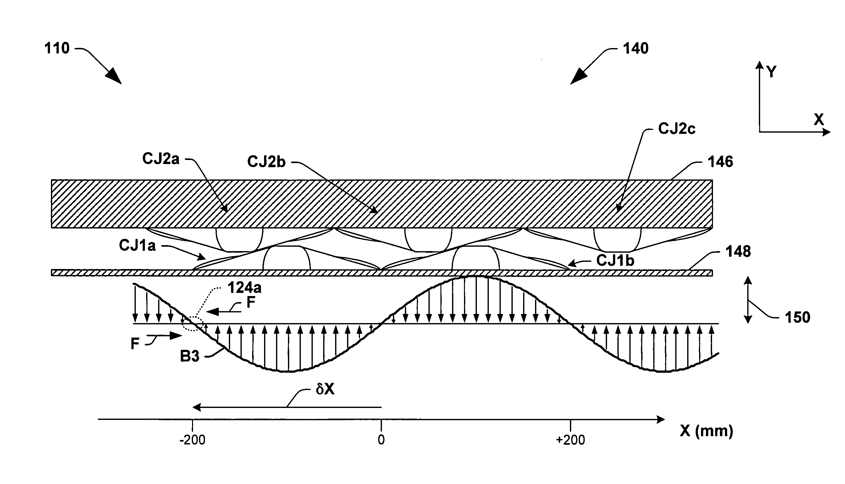
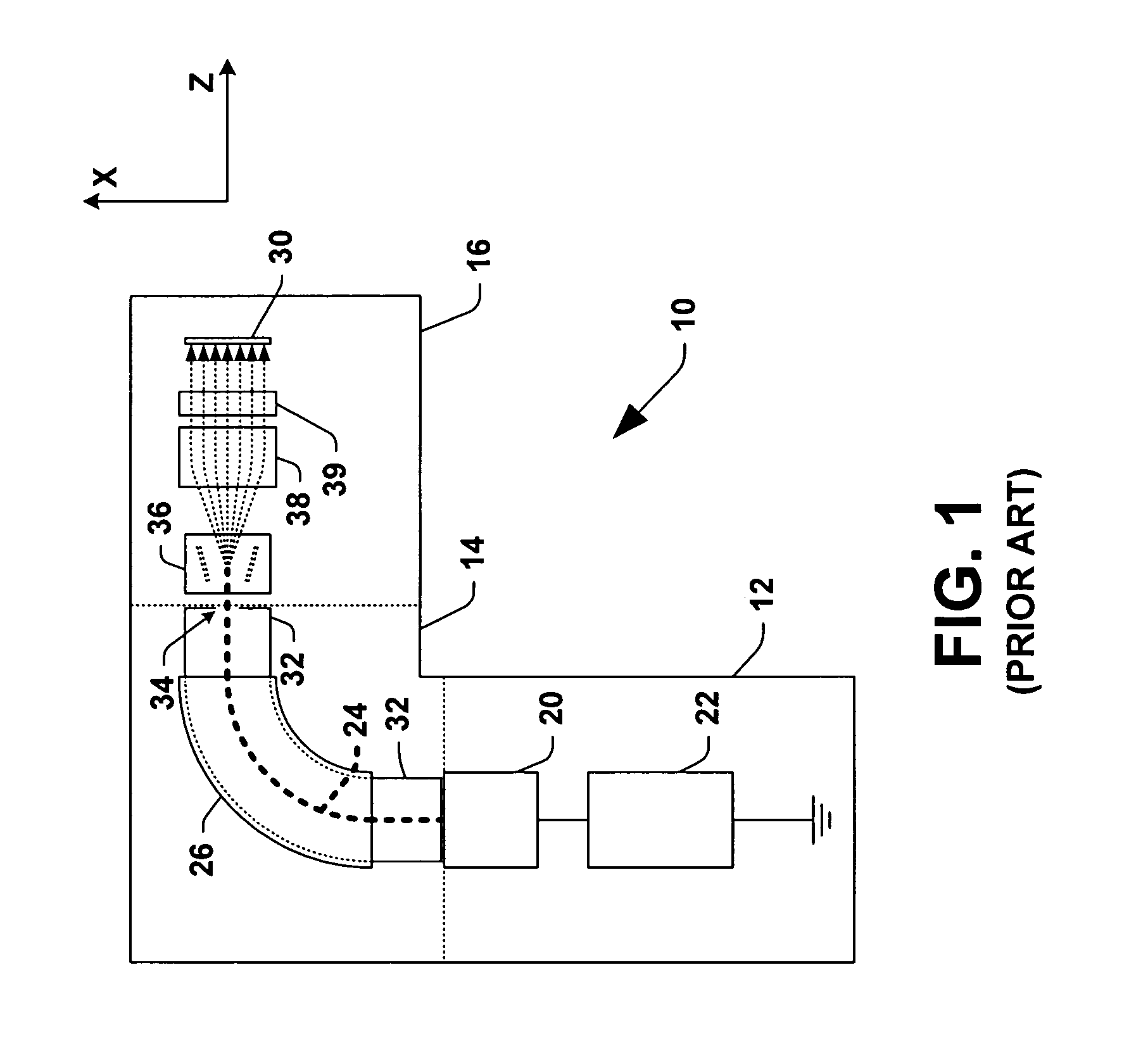
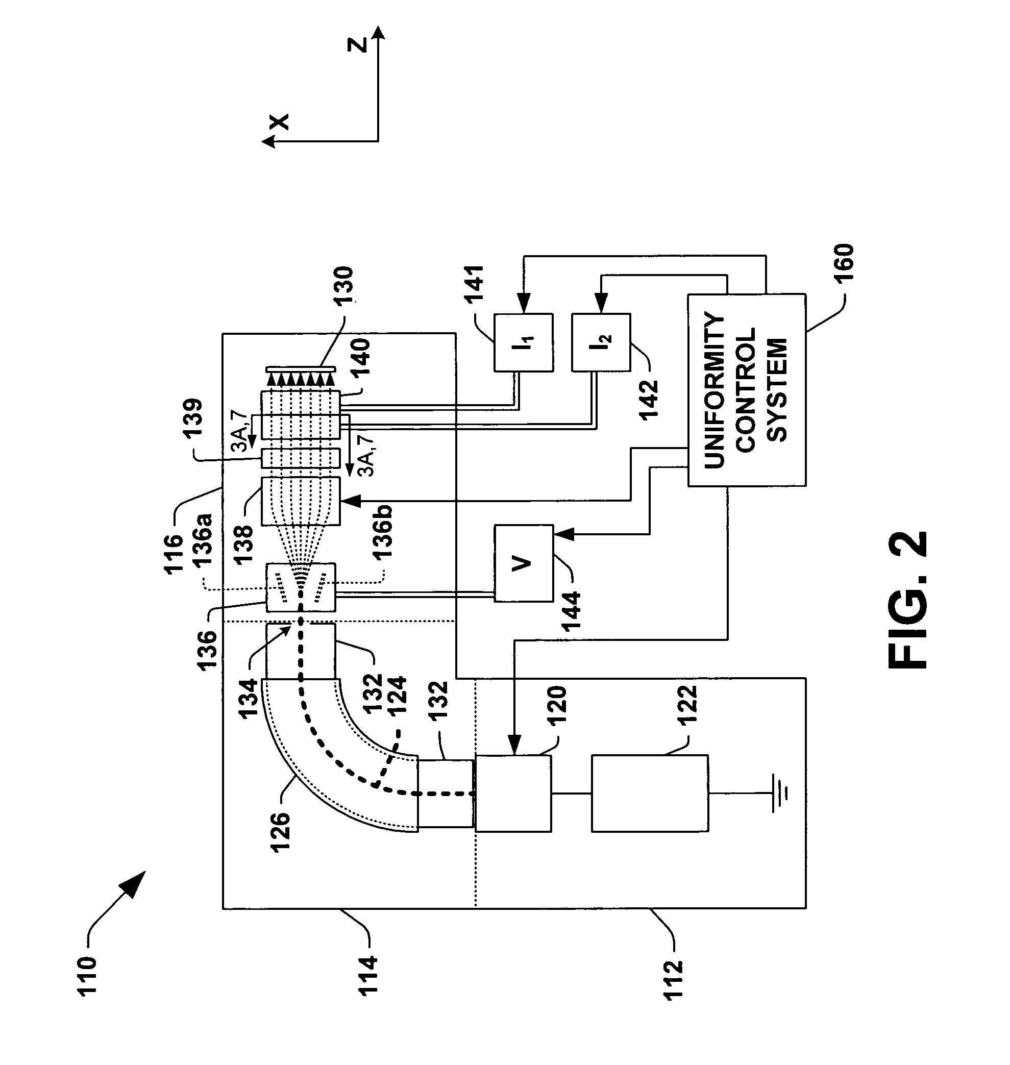
[0028]Referring initially to FIG. 2, an exemplary ion implantation system (ion implanter) 110 is illustrated, having a beam scanner 136 and a beam focusing system 140 in accordance with one or more aspects of the invention. The exemplary ion implantation system 110 comprises a terminal 112, a beamline assembly 114, and an end station 116 that forms a process chamber in which a mass analyzed and scanned ion beam 124 is directed to a workpiece location. An ion source 120 in the terminal 112 is powered by a power supply 122 to provide an extracted ion beam 124 to the beamline assembly 114, wherein the source 120 includes one or more extraction electrodes (not shown) to extract ions from the source chamber and thereby to direct the extracted ion beam 124 to...


PUM


Abstract

Systems and methods are provided for focusing a scanned ion beam in an ion implanter. A beam focusing system is provided, comprising first and second magnets providing corresponding magnetic fields that cooperatively provide a magnetic focusing field having a time-varying focusing field center generally corresponding to a time-varying beam position of a scanned ion beam along a scan direction. Methods are presented, comprising providing a focusing field having a focusing field center in the scan plane, and dynamically adjusting the focusing field such that the focusing field center is generally coincident with a time-varying beam position of the scanned ion beam along the scan direction.

Description

FIELD OF THE INVENTION[0001]The present invention relates generally to ion implantation systems, and more specifically to focusing apparatus and methods for focusing scanned ion beams in ion implantation systems.BACKGROUND OF THE INVENTION[0002]In the manufacture of semiconductor devices and other products, ion implantation is used to dope semiconductor wafers, display panels, or other workpieces with impurities. Ion implanters or ion implantation systems treat a workpiece with an ion beam, to produce n or p-type doped regions or to form passivation layers in the workpiece. When used for doping semiconductor wafers, the ion implantation system injects a selected ion species into the wafer to produce the desired extrinsic material, wherein implanting ions generated from source materials such as antimony, arsenic or phosphorus results in n-type extrinsic material wafers, and implanting materials such as boron, gallium or indium creates p-type extrinsic material portions in a semicondu...

Claims


Application Information

Patent Timeline
Patent Type & Authority Patents(United States)
IPC IPC(8): H01L21/324H01J37/317H01J49/30
CPCH01J37/3171H01J37/147H01J37/30H01J37/317
Inventor BENVENISTE, VICTOR M.KELLERMAN, PETER L.
Owner AXCELIS TECHNOLOGIES
Why Eureka
Try Eureka