Sealing agent for a foil sealed lamp

a sealing agent and foil technology, applied in the manufacture of cold cathode, electric discharge tube/lamp, electric discharge system, etc., can solve the problems of affecting the use affecting the service life of the lamp, so as to prolong the use life and improve the heat resistance of the sealing portion. , the effect of improving the temperatur

Active Publication Date: 2006-03-28
USHIO DENKI KK
View PDF9 Cites 3 Cited by
  • Summary
  • Abstract
  • Description
  • Claims
  • Application Information

AI Technical Summary

Benefits of technology

[0016]It is an object of the present invention to provide a lamp having high heat-resistant temperature and a long use lifetime.
[0017]It is another object of the present invention to prevent oxidization of a metallic foil and a lead rod.
[0021]The lamp according to the present invention, has a structure in which a gap formed on an outer surface of the lead rod is filled with sealing agent made of rubidium oxide or cesium oxide, and glass comprising boron and oxide bismuth oxide as main components is attached to an outer end surface of the sealing portion(s) thereby closing an entrance of air on the outer end surface of the sealing portion(s). According to such a structure, since the lead rod(s) and foil(s), which are exposed to the oxidation environment, are sufficiently shut out from outside air, a heat-resistant temperature of sealing portion is improved. Furthermore, it is possible to extend the use lifetime in a high temperature.

Problems solved by technology

With this, since such super high pressure mercury lamps themselves become miniaturized, and in such lamps, high illumination is realized, there is tendency of a temperature rise in each part.
As a result, the sealing portions are cracked, or the metallic foils are melt due to the oxidization of the metallic foils and the lead rods thereby causing breakdown of the lamp at an early stage.
However, the technology disclosed in Japanese Patent Number 7-105212 has a problem that it takes a fairly long time at a relatively low temperature to dry the aqueous solution of alkali metal silicate.
That is, although during the drying process the viscosity of the aqueous solution of alkali metal silicate gradually becomes high and in the last result becomes a glassy coat, moisture and / or gas may be trapped in the high viscous glassy coat where a drying temperature is too high, or where drying time is too short.
In this case, a heat-resistant temperature of the sealing portions may not be improved and a lifetime of the sealing portions it may not be extended.
Moreover, according to the technology disclosed in Japanese Patent No. 7-19582, there is a problem that in order to acquire good flowability, it is necessary to heat the sealing portions to a large extent in a process of filling with low-melting glass a gap formed between the sealing portion and the outer surface of a lead rod.
Furthermore, since the low-melting glass filler contains lead oxide, it is not desirable in view of environmental issues.
Furthermore, when the lamp according to the technology disclosed in Japanese Patent No. 7-105212, was put in an electric furnace, which was continuously operated at 500 to 550 degrees Celsius, and a heat-resistant test of sealing portions was performed, the following problems arose:
Therefore, with the technology disclosed in Japanese Patent No. 7-19582, the sealing portions whose temperature reaches greater than 500 degree Celsius while the lamp is turned on, cannot have a sufficient heat-resistant temperature and a use lifetime.

Method used


Image

  • Sealing agent for a foil sealed lamp
  • Sealing agent for a foil sealed lamp
  • Sealing agent for a foil sealed lamp

Examples


Embodiment Construction

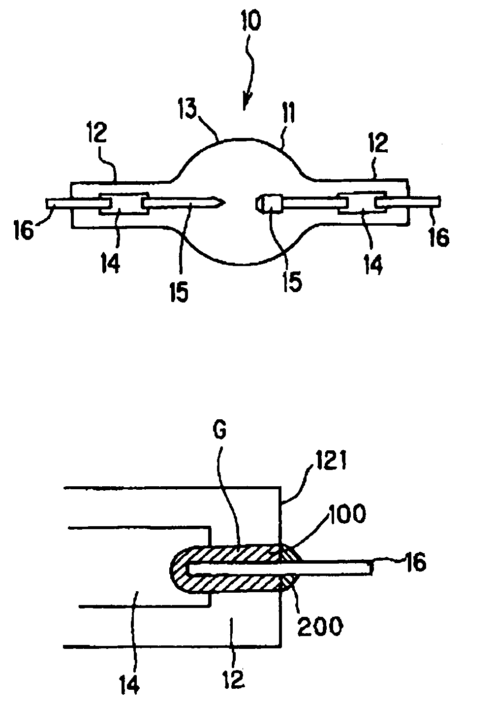
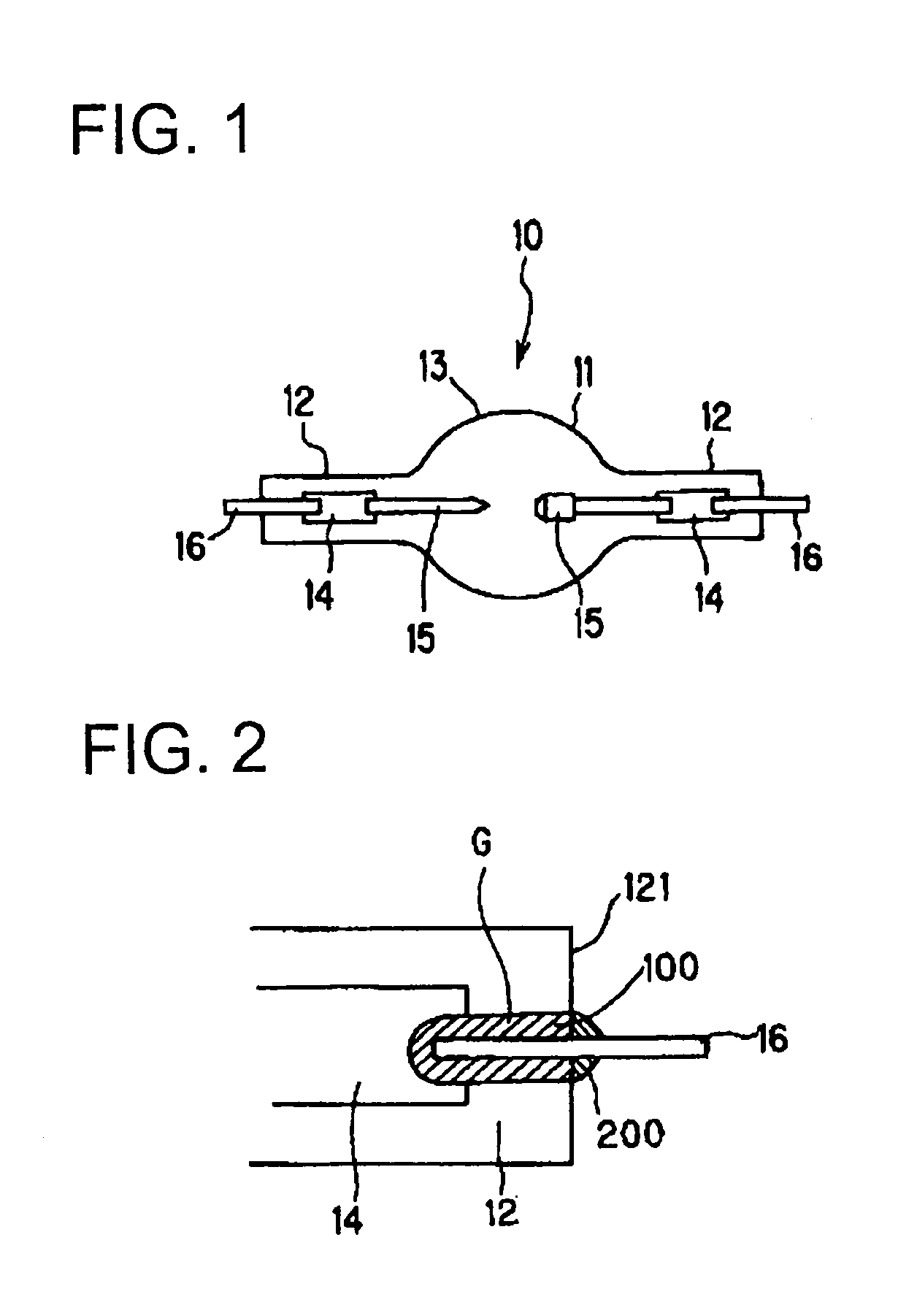
[0030]FIG. 1 is a diagram explaining the structure of a lamp according to the present invention.

[0031]A discharge lamp 10 has a discharge container 13 made of quartz glass and comprising a light emitting portion 11, and sealing portions 12 which are formed at both end of the light emitting portion 11. Each of the sealing portions 12 is air tightly sealed so as to bury a metallic foil 14 made of molybdenum. A pair of electrodes 15 are extended into the light emitting portion 11, each of which is connected to one end of each metallic foil 14. The other end of each metallic foil 14 is connected to a lead rod 16 made of molybdenum or tungsten so that the lead rod 16 extends outward from an end surface of the sealing portion 12. Furthermore, in a discharge container 13, 150 to 350 mg / cc mercury is enclosed as a light emitting substance.

[0032]FIG. 2 is an enlarged view of one of the sealing portions 12 in the lamp according to the present invention.

[0033]A gap G formed between the sealing...


PUM


Abstract

In a foil sealed lamp, a lamp container made of transparent material, has at least one sealing portion made of molybdenum wherein a metallic foil is buried, a light emitting section which is connected to one end of the metallic foil and a lead rod extending outward and connected to other end of the metallic foil, and wherein, in the sealing portion, a gap formed around a circumference portion of the lead rod is filled with sealing agent made of rubidium oxide or cesium oxide, and glass having boron oxide and bismuth oxide as principal components is coated on an outer end surface of the sealing portion so as to close the gap.

Description

TECHNICAL FIELD OF THE INVENTION[0001]The present invention relates to a lamp having a structure in which a metallic foil made of molybdenum is air-tightly sealed in a sealing portion(s) of a lamp container having a light emitting portion and the sealing portion(s) and made of transparent material, and more specifically, to a lamp in which the sealing portion(s) reaches a high temperature when the lamp is turned on.DESCRIPTION OF RELATED ART[0002]As a lamp having a foil seal structure in which a metallic foil made of molybdenum is buried in the sealing portion(s), for example, an incandescent light bulb and a discharge lamp are known. A discharge lamp in which a foil seal structure is adopted can be classified into several types of lamps in view of a light emitting substance and / or pressure in an arc tube. In view of the light emitting substance, there are a mercury lamp containing mercury as a light emitting substance, a metal halide lamp containing a mixture of metal vapor and a d...

Claims


Application Information

Patent Timeline
Patent Type & Authority Patents(United States)
IPC IPC(8): H01J17/16H01J9/32H01J61/36H01J61/86H01K1/38H01K3/20
CPCH01J9/326H01J61/368H01K3/20H01K1/38H01J61/86
Inventor OKAMOTO, TOSHIYUKITAGAWA, YUKIHARU
Owner USHIO DENKI KK
Why Eureka
Try Eureka