
Repair method for structure and repair welding apparatus

a technology for structural repair and welding equipment, which is applied in the direction of arc welding equipment, nuclear engineering, nuclear elements, etc., can solve the problems of tig welding repair being unsuitable for structure, deterioration of the base material of the structure, and weld flaws, so as to reduce tensile residual stress and inhibit cracks

Inactive Publication Date: 2006-04-04
KK TOSHIBA
View PDF14 Cites 29 Cited by
  • Summary
  • Abstract
  • Description
  • Claims
  • Application Information

AI Technical Summary

Benefits of technology

[0010]Accordingly, an object of the present invention is to provide a structure repair method and a repair welding apparatus, to remove a crack occurring in a structure or to seal an open portion of the surface of a crack, so as to inhibit recurrence of a crack by reducing tensile residual stress in the surface portion of the repair weld portion.
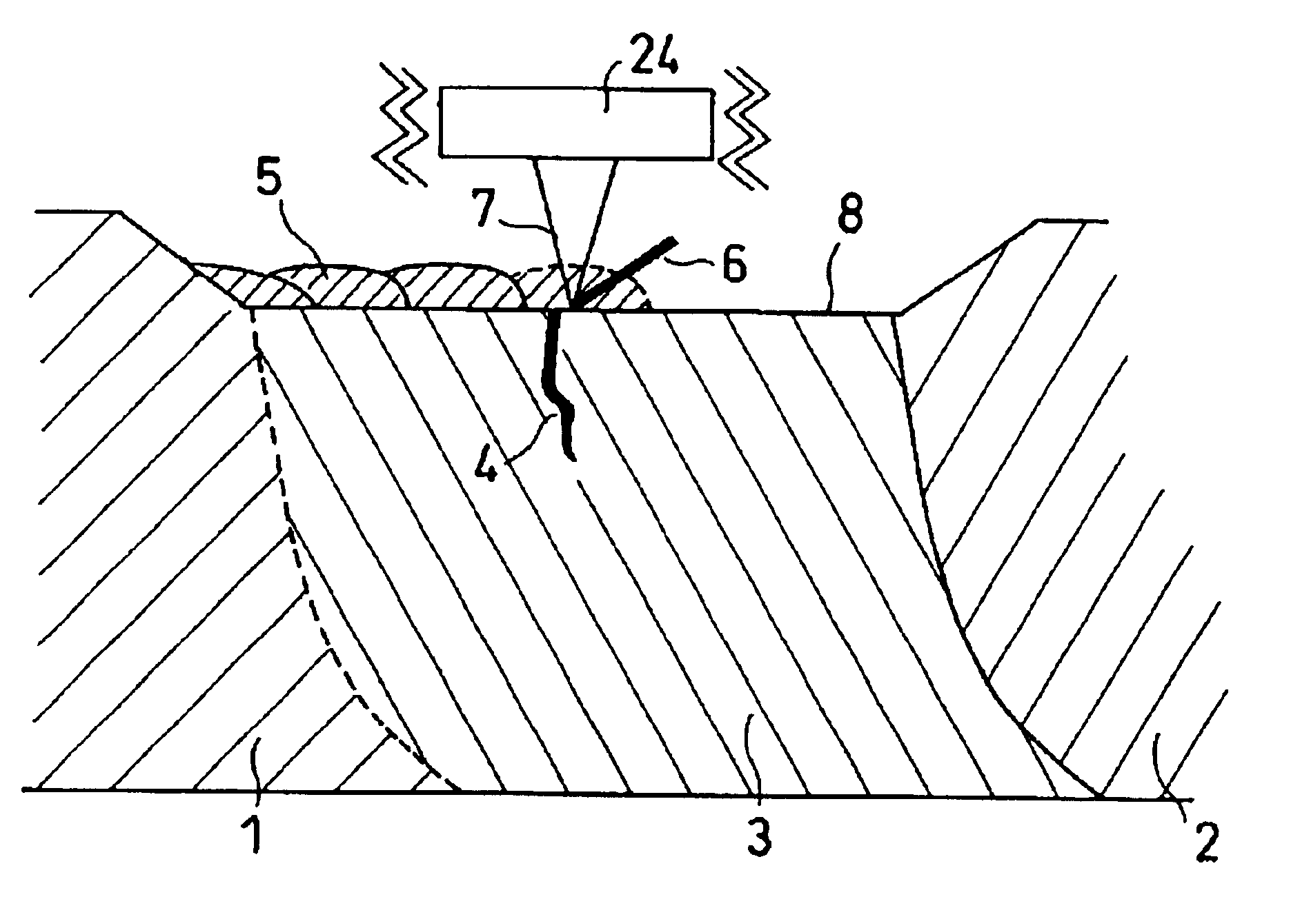
[0011]According to one aspect of the present invention, there is provided a repair method for a structure having an open flaw in a welding heat affected portion, including, removing at least a part of the open flaw and thereby forming a concave portion in the welding heat affected portion, forming build-up weld layers so as to fill the concave portion, and treating a surface of the build-up layers to reduce tensile residual stress by means of at least one of laser peening, shot blasting and water jet machining. For instance, this repair method may be successfully conducted underwater and on neutron-irradiated materials.
[0012]According to another aspect of the present invention, there is provided a repair method for a structure having an open flaw in a welding heat affected portion, including, cleaning a surface of the welding heat affected portion, forming build-up weld layers on a region including the open flaw to seal the open flaw therewith, and treating a surface of the build-up layers to reduce tensile residual stress by means of at least one of laser peening, shot blasting and water jet machining. For instance, this repair method may be successfully conducted underwater and on neutron-irradiated materials.

Problems solved by technology

However, TIG welding repair may be unsuitable for structure exposed to neutrons during long-term operation within a nuclear reactor.
Neutron exposure may cause deterioration of the base material of a structure.
If TIG welding is applied to such a base material deteriorated due to neutron irradiation, the amount of inputted heat may cause weld flaws.
Since the TIG welding involves melting a base material with an electric arc generated between the base material and a torch electrode, the arc becomes unstable when an oxide film is present on the base material.
The TIG weld arc may also become unstable when an oxide film is deposited on or water enters an inner portion of an open flaw (i.e., crack).
For this reason, stable welding operations cannot be performed when the base metal or the flaw to be repaired have an oxide layer or inner water.
According to this repair method, a crack removed by such repair work leaves behind a tensile residual stress on the surface of the repair weld zone due to the repair build-up welding.
Therefore, there is the possibility of a crack recurring.
However, the occurrence of tensile residual stress cannot be avoided due to shrinkage of the repaired weld zone during the repair welding and re-melting operations.
Thus, this repair method does not eliminate the possibility that cracking will recur.
In the above-mentioned conventional repair methods, the occurrence of tensile residual stress in a repaired weld zone is unavoidable.
Consequently, there is the possibility of cracks recurring, such as stress corrosion cracking, after the execution of a repair welding operation.

Method used


Image

  • Repair method for structure and repair welding apparatus
  • Repair method for structure and repair welding apparatus
  • Repair method for structure and repair welding apparatus

Examples


first embodiment

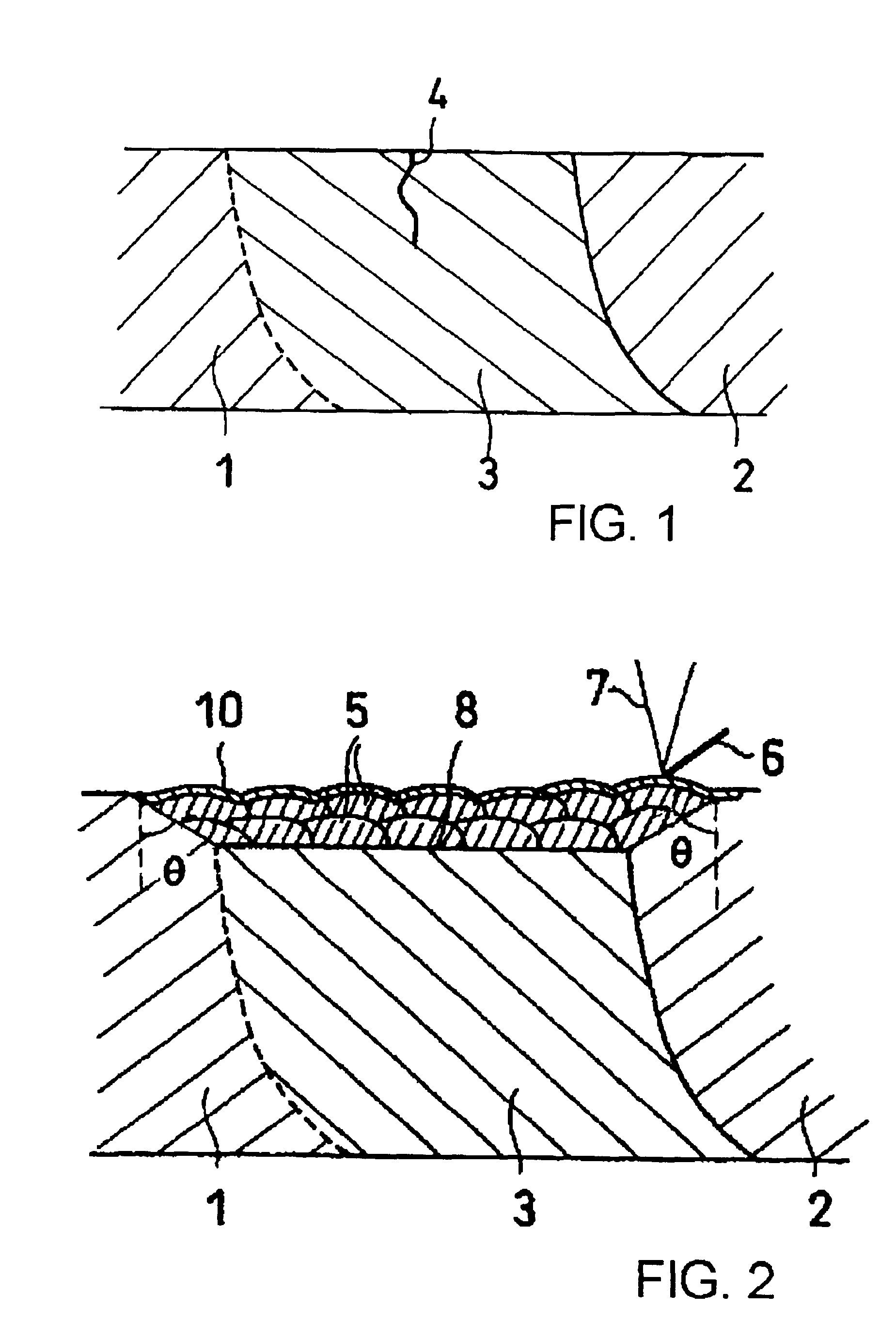
[0023]A structure, an object to be repaired is, for example, as shown in FIG. 1. Namely, the structure member 1 is formed of a Fe alloy (iron alloy), such as austenite-based stainless steel, or a Ni alloy (nickel alloy), such as Inconel. When the structure member 1 is welded at a welding portion 2, a welding heat-affected portion 3 is generated. In the welding heat-affected portion 3, Cr carbide (chromium carbide) is deposited on grain boundaries of the material. When this condition occurs, the welding heat-affected portion 3 is said to be sensitized. Thus, there is the possibility that a crack-like open flaw 4 exists or may occur in the welding heat-affected portion 3.

[0024]A repair method including two steps, i.e. a build-up welding step and a step of reducing tensile residual stress, will be described as a first embodiment of the present invention with reference to FIG. 2. First, as a pretreatment process, crud, that is a metal oxide of a radioactive corrosion product, or an oxid...

second embodiment

[0041]A repair method including two steps, i.e. a build-up welding step and a step of reducing tensile residual stress, carried out without removing an open flaw, will be described as a second embodiment of the present invention with reference to FIG. 6.

[0042]First, as a pretreatment step, crud or an oxide film sticking to a surface of a welding heat-affected portion 3 is removed, and the surface portion of the welding heat-affected portion 3 is cleaned. This cleaning operation is accomplished by irradiation of a laser beam or mechanical grinding, such as using a grinder or a flap wheel. When irradiation of a laser beam is used, only the surface portion of the welding heat-affected portion 3 is momentarily heated by pulsing the laser with a pulse width of the laser beam between 5 and 100 nanoseconds. This enables the crud or the oxide film to be removed from the surface.

[0043]After the surface portion of the welding heat-affected portion 3 is cleaned, a visual external inspection an...


PUM

PropertyMeasurementUnit
sizeaaaaaaaaaa
sizeaaaaaaaaaa
angleaaaaaaaaaa

Abstract

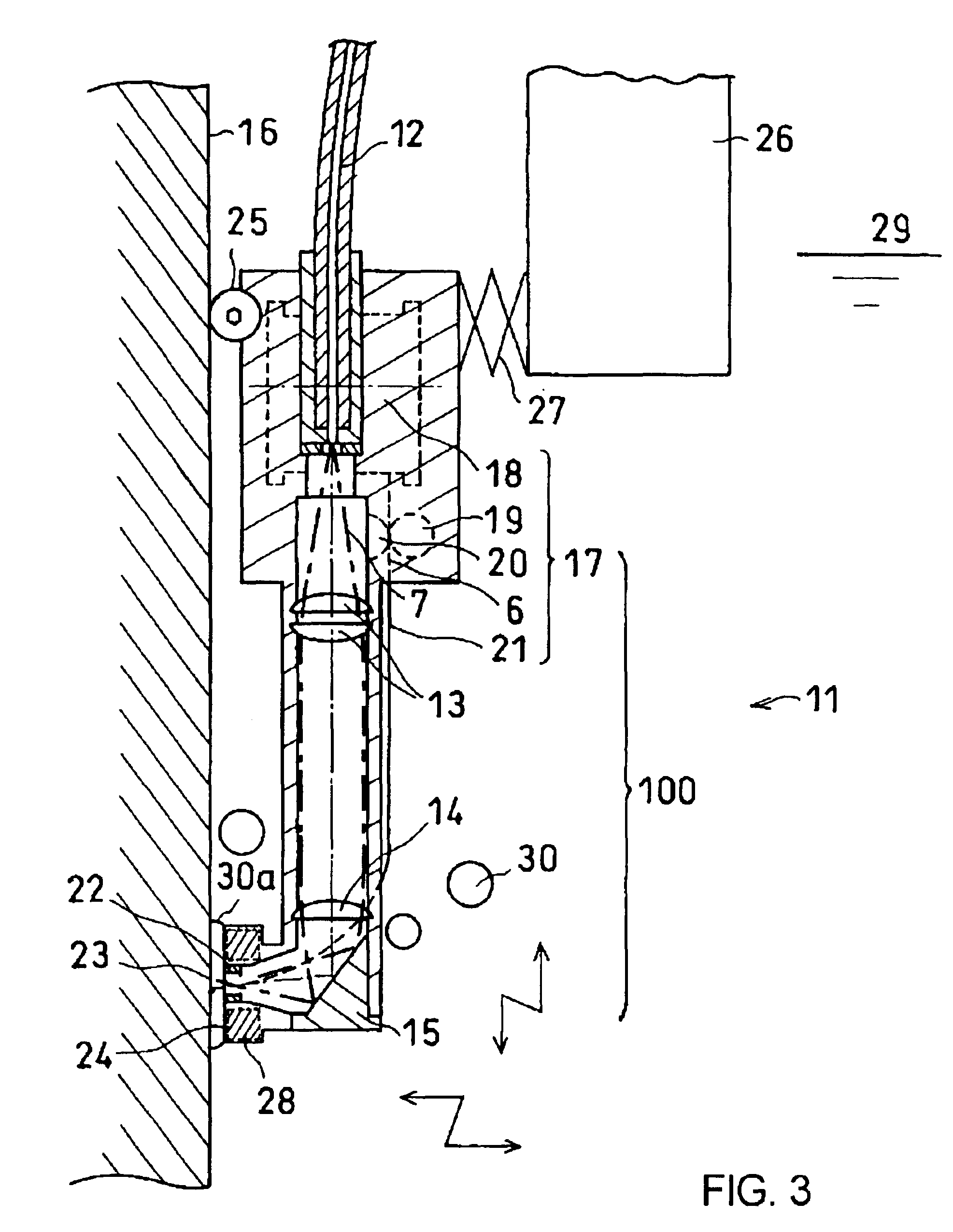
A repair method for a structure having an open flaw in a welding heat affected portion, including, removing at least a part of the open flaw and thereby forming a concave portion in the welding heat affected portion, forming build-up weld layers so as to fill the concave portion, treating a surface of the build-up layers to reduce tensile residual stress by means of at least one of laser peening, shot blasting and water jet machining. Also disclosed is an apparatus suitable for carrying out the repair method.

Description

CROSS-REFERENCE TO RELATED APPLICATIONS[0001]This application is based upon and claims the benefit of priority from the prior Japanese Patent Application No. 2001-241725 filed on Aug. 9, 2001, the entire contents of which are incorporated herein by reference.BACKGROUND OF THE INVENTION[0002]1. Field of the Invention[0003]This invention relates to a repair method and a repair welding apparatus for a structure, adapted to prevent an accident due to cracking of a structure and prolong a lifetime of a structure, and more particularly to a structure repair method and a repair welding apparatus, adapted to be applied to a structure in which stress corrosion cracking or fatigue cracking occurs.[0004]2. Description of the Related Art[0005]When a crack occurs in a structure, a machine and the like (which will hereinafter be referred to as a structure), for example, in a nuclear reactor, the structure may be exchanged as a whole, or repaired by attaching a reinforcing metal material to the cr...

Claims


Application Information

Patent Timeline
Patent Type & Authority Patents(United States)
IPC IPC(8): B23K31/00E04G23/02B23K9/04B23K26/28B23K26/34B23P6/00B23P6/04B24C1/10C21D7/06C21D10/00G21C19/02
CPCB23K26/123B23K35/0227B23K26/1494B23K26/203B23K26/28B23P6/00B23P6/04B23K26/3206B23K26/3213B23K26/345B23K35/0255B23K35/0261B23K26/1417C21D7/06C21D10/005B23K26/32B23K26/146B23K26/211B23K26/342B23K2103/02B23K2103/05B23K2103/26B23K2103/50
Inventor TAMURA, MASATAKAMAKINO, YOSHINOBUKONO, WATARUKIMURA, SEIICHIROSUEZONO, NOBUICHITAKAHASHI, HIDENORI
Owner KK TOSHIBA
Learn More