Thermal flow simulation for casting/molding processes

Inactive Publication Date: 2006-04-04
MERCURY MARINE
View PDF86 Cites 135 Cited by
  • Summary
  • Abstract
  • Description
  • Claims
  • Application Information

AI Technical Summary

Benefits of technology

[0013]Accordingly, an object of the present invention is to provide an improved me

Problems solved by technology

The conventional models generally provide no means for determining whether or not input conditions are appropriate.
Conventional fluid flow models lack many refinements which would enable better estimation of the boundary conditions, and hence often fail to achieve an accurate simulation.
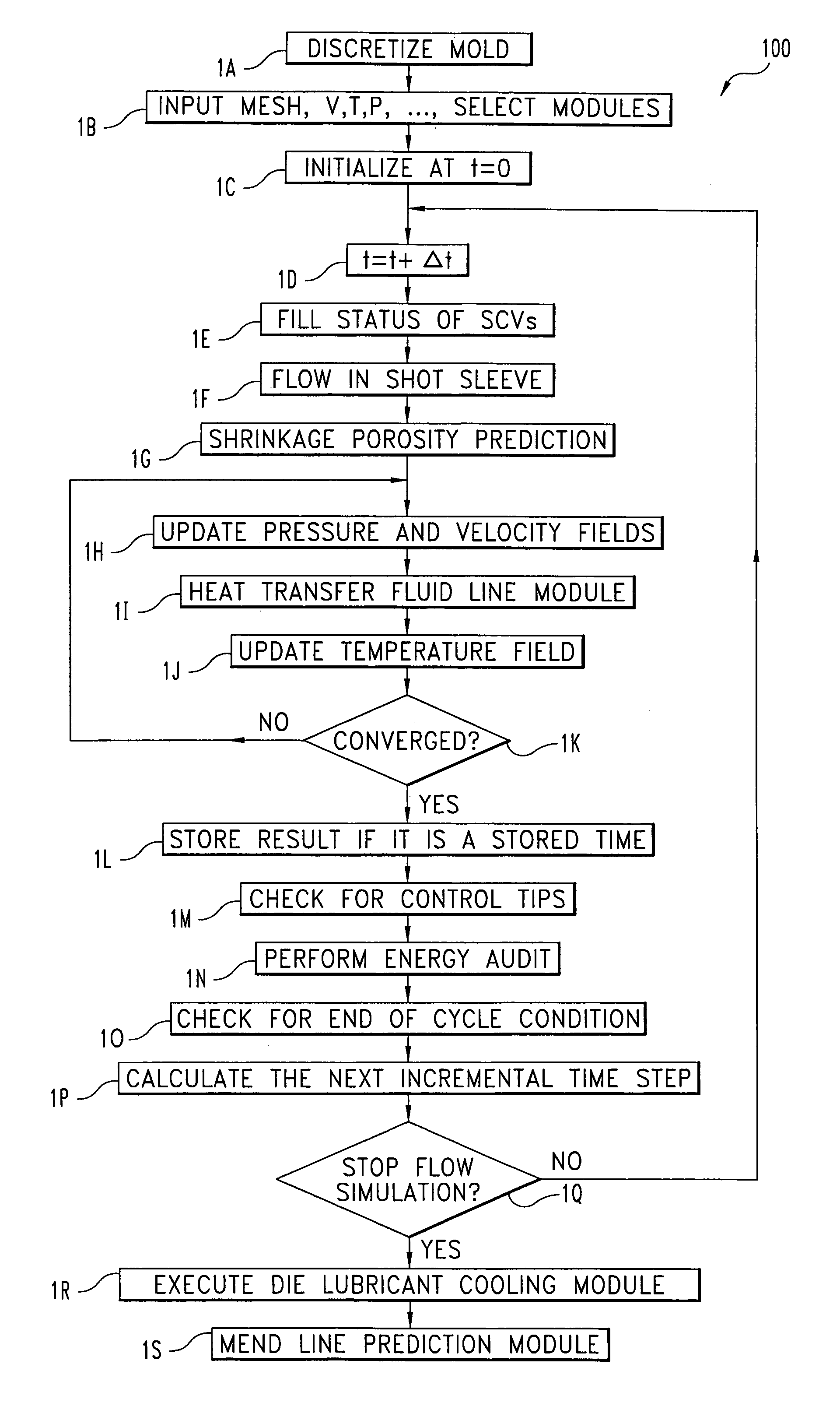
Due to discontinuity created by the moving ram and the resulting instability in numerical models, many prior art models start the simulation at the gate entrance and make the assumption that the pressure or velocity applied by the ram is uniform across the gate surface.
In practice, the molten metal in the shot sleeve always has some temperature variation, and the pressure applied to the billet across the ram face is non-uniform.
This non-uniformity of temperature pressure and material flow in the short sleeve, if not corrected, ultimately compromises the accuracy of the mass flux computation of a flow model.
Since the HTF's viscosity changes with its temperature, which varies through the entire loop, it is very difficult for the user to determine the coefficient, as the Reynolds number and Prandtl number are not constant.
Shrinkage porosity formation is a common problem for metal casting process.
If there is no additional material fed into the cavity, the net volume of the metal will become less than that of the cavity and shrinkage porosity will result.
Depending on its size and distribution, shrinkage porosity could compromise the mechanical properties of a product, especially its elongation and fatigue strength, significantly.
For pressure tight products, shrinkage

Method used


Image

  • Thermal flow simulation for casting/molding processes
  • Thermal flow simulation for casting/molding processes
  • Thermal flow simulation for casting/molding processes

Examples


Embodiment Construction

[0027]For the purposes of promoting an understanding of the principles of the invention, reference will now be made to the embodiment illustrated in the drawings and specific language will be used to describe the same. It will nevertheless be understood that no limitation of the scope of the invention is thereby intended. Any alterations and further modifications in the illustrated device, and any further applications of the principles of the invention as illustrated therein being contemplated as would normally occur to one skilled in the art to which the invention relates are also included.

[0028]An embodiment of the present invention is a numerical method for computer simulation of the behavior of an incompressible, viscous fluid during a casting / molding process. The illustrated method is based on classical fluid dynamic models, and numerically (through the use of a computation device, generally a computer) obtains solutions to the governing equations at user defined time intervals...


PUM

PropertyMeasurementUnit
Temperatureaaaaaaaaaa
Timeaaaaaaaaaa
Pressureaaaaaaaaaa

Abstract

A numerical procedure for simulating the behavior of incompressible, viscous fluid in a casting/molding process. The method is based on classical fluid dynamic equations and uses control volume-finite element and numerical techniques to solve the momentum and energy equations to obtain solution for the variable parameters. The method incorporates five additional modules which simulate fluid flow in the shot sleeve, heat transfer between the die and the heat transfer fluid, die cooling by lubricant, formation of mend line. These additional simulation modules produce realistic boundary conditions, and replace many of the assumptions that would have to be made, to solve the governing equations. These added improvements ensure a faster convergence of the numerical solution and a more realistic simulation of the die casting process.

Description

CROSS REFERENCE TO RELATED APPLICATION[0001]The present application relates to a commonly owned, issued U.S. Patent, entitled EQUAL ORDER METHOD FOR FLUID FLOW SIMULATION, filed on even day herewith by the same inventive entity. The referenced application is incorporated herein by reference in its entirety.FIELD OF THE INVENTION[0002]This invention relates to a method for simulating the behavior of a fluid during a casting / molding process, in particular, to a numerical method for simulating incompressible, viscous melt flow in a die cavity.BACKGROUND OF THE INVENTION[0003]In manufacturing casting / molding processes, for product quality of the molded article, it is of importance to optimize the mold design and the process conditions. Conventionally, such optimization is attained after many trial and error experiments which are repeated on the basis of the rule of thumb of an expert. With the advance in computer technology, it has become possible to analyze flow behavior of a material ...

Claims


Application Information

Patent Timeline
IPC IPC(8): G06G7/48B22D46/00B22D17/32B29C45/76G06F17/50
CPCB22D17/32B29C45/7693G06F17/5018G06F2217/80G06F2217/16G06F2217/41G06F30/23G06F2111/10G06F2113/22G06F2119/08
Inventor WAITE, DAVID MARCWANG, SHAUPOHNIEH, JENN-YEU
Owner MERCURY MARINE
Why Eureka
Try Eureka