Compacting apparatus

a technology of compacting apparatus and clamping rod, which is applied in the field of presses, can solve the problems of large amount of metal used in the fabrication process, small amount of waste in castings, and low priority of metal waste produced in most fabrication shops, and achieves the effects of convenient clearing of jams, high density, and more efficient and economical metal recycling

Inactive Publication Date: 2006-04-18
RALICKI DANIEL J
View PDF24 Cites 21 Cited by
  • Summary
  • Abstract
  • Description
  • Claims
  • Application Information

AI Technical Summary

Benefits of technology

[0020]In a second manifestation, the invention is a compacting apparatus for compacting scrap material entrained with fluid to form pellets and extract fluid therefrom, for enabling more efficient and economical recycling of the metal and separate handling of machining fluid. A cylinder has an opening for introduction of scrap material, and a first end and a second end distal thereto. A compactor piston is adjacent to and closes the first end of the cylinder. A moveable gate having an aperture and a pressure face is moveable between a first position in which the pressure face selectively blocks passage of scrap material substantially from the second end of the cylinder and a second position in which the gate aperture is aligned with the second end to selectively permit passage of scrap material from the second end of the cylinder. The pressure face has at least one radial drain channel extending radially from the pressure face for draining fluid extracted from waste product during the compacting process. The aperture is spaced from and vertically above the pressure face, whereby extracted fluid is deterred from passing through the aperture by gravitational force.
[0021]In a third manifestation, the invention is a method for compacting scrap material entrained with fluid to form pellets and extracting the fluid therefrom, for recycling of pellets and separate handling of fluid. According to the method, scrap material is collected in a supply hopper. A plurality of augers are provided adjacent the bottom of the supply hopper. Individual ones of the plurality of augers are rotated independently from other ones. Clumps within the scrap material being carried forward by the augers are sheared against at least one, and preferably several shear bars cooperating with the plurality of augers. In a more specific manifestation of this method, a load on each of the individual ones of the plurality of augers is sensed to determine when an individual one of the plurality of augers is jammed. The rotating of jammed individual ones of the plurality of augers is controlled responsive to sensing the jam, to in one mode stop and in a second mode reverse a direction of rotation to free the jam. The load on the jammed individual one of the plurality of augers is detected subsequent to the controlling step to determine whether the jam still exists, and, if so, the other ones of the plurality of augers are continued to operate until the supply hopper is nearly or otherwise emptied, thereby greatly facilitating the clearing of the jam.
[0022]A first object of the invention is to provide a compactor suitable for forming solid slugs or pucks of metal, of high density and low volume, and with minimal or no entrained fluid. A second object of the invention is to reliably collect fluid exuded during the formation of the metal slug separately from the slug, thereby avoiding or minimizing the need for undesirable drying of pellets after compacting. Another object of the present invention is to provide a very reliable feed auger suited for properly feeding, and where appropriate, cutting long spirals and diverse materials. A further object of the invention is to controllably drive each auger separately, thereby facilitating reversal thereof. In the event of a bind, yet another object of the present invention is to enable the remaining augers to operate, to clear the hopper and provide access to the bound auger and avoid the need to manually empty the in-feed hopper.

Problems solved by technology

Consequently, even where the materials are primarily non-metallic, there is often a significant amount of metal used in the fabrication thereof.
These castings may likewise have a small amount of waste, such as the neck portion where the metal passes into the body of the mold.
Consequently, metal wastes produced in most fabrication shops have not heretofore received much priority.
However, the volume of scrap produced from machining operations is very high compared to the actual weight of metal contained therein.
The hauling of this high volume, low weight scrap to central recyclers is, quite simply, inefficient and costly.
Even where this material is attempted to be recycled, the ordinary recycling processes have not worked well.
Unfortunately, the thin metal spirals tends to have very large surface area which is typically readily oxidized.
This thin metal will often burn, instead of melting, and so will produce ash and soot instead of the desired liquid metal.
Further, the machining oil produces large quantities of undesirable soot.
Between the high transport costs and poor recycling yields, the practice has more frequently been landfill disposal or the like.
Unfortunately, the high quantity of oil in the metal has been recognized to be a hazardous waste, subject to regulation by various environmental regulatory agencies.
However, several deficiencies have been noted in the Bendzick approach.
One limitation arises from the vertical orientation of pellet formation and discharge.
Consequently, it is rather difficult to effectively separate fluid from pellet, other than by the undesirable drying of pellets after compacting.
However, and as noted by Bendzick, the formation of ordinary drainage channels, such as through a screen or the like, is very much complicated by the intense pressures used in the pressing of metal shavings and the like into pellets or slugs.
Unfortunately, these spirals may readily become intertwined with adjacent spirals when being moved about by the feed augers.
In the prior art such as Bendzick, this has resulted in a need to completely empty the in-feed hopper, until the jam, which is usually at the bottom adjacent the auger, can be accessed and cleared.
As may be apparent, such jam-clearing operations are very time consuming and dangerous, since these shavings are usually quite sharp and prone to springing about unexpectedly.
Consequently, many shops have avoided implementing any compacting operations at all, owing to the lack of adequate reliability and efficiency of operation of these prior art machines.
Nevertheless, these patents do not either singly or in combination teach a method or apparatus to overcome the aforementioned deficiencies in the Bendzick patents.

Method used


Image

  • Compacting apparatus
  • Compacting apparatus
  • Compacting apparatus

Examples


Embodiment Construction

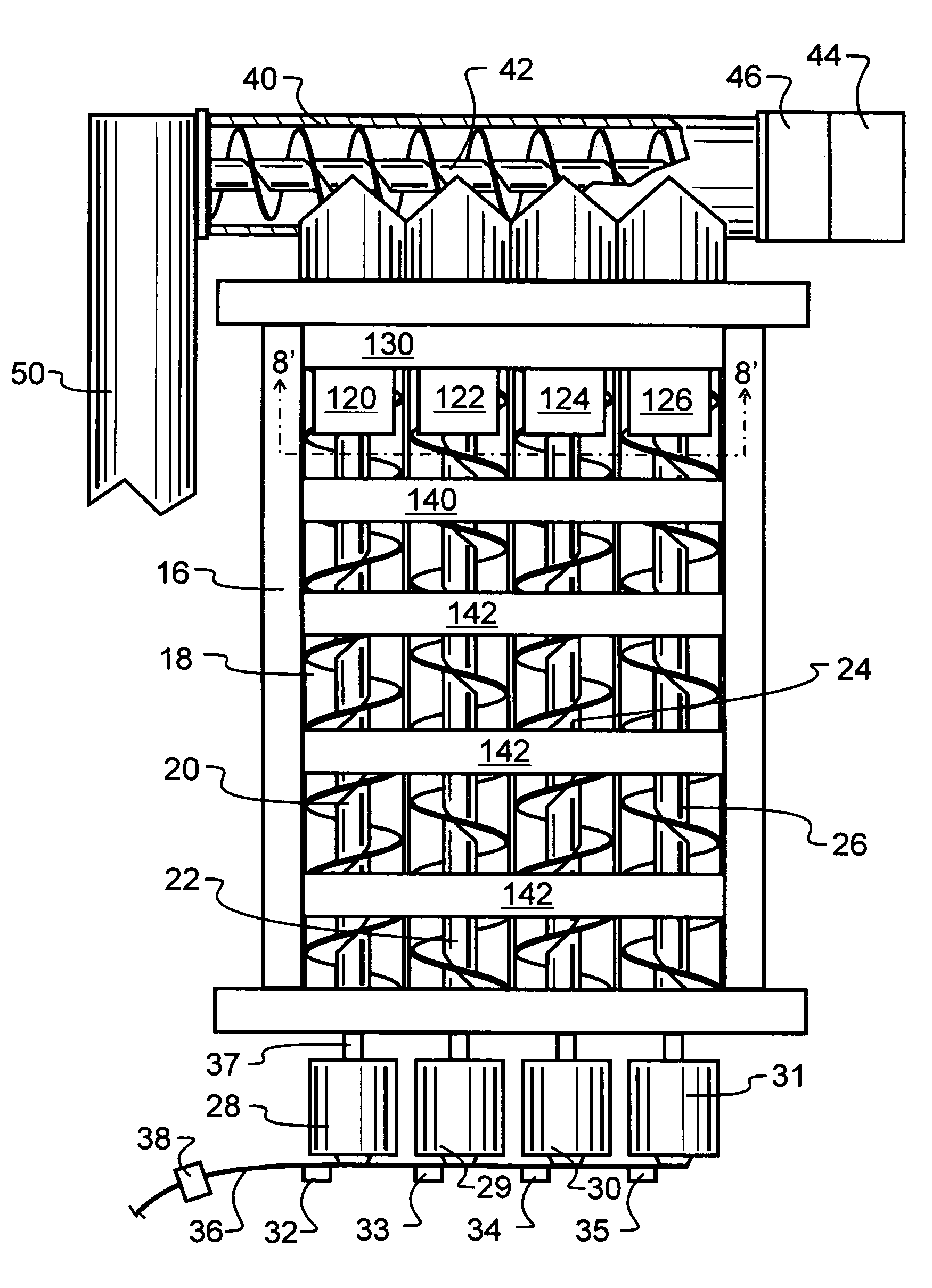
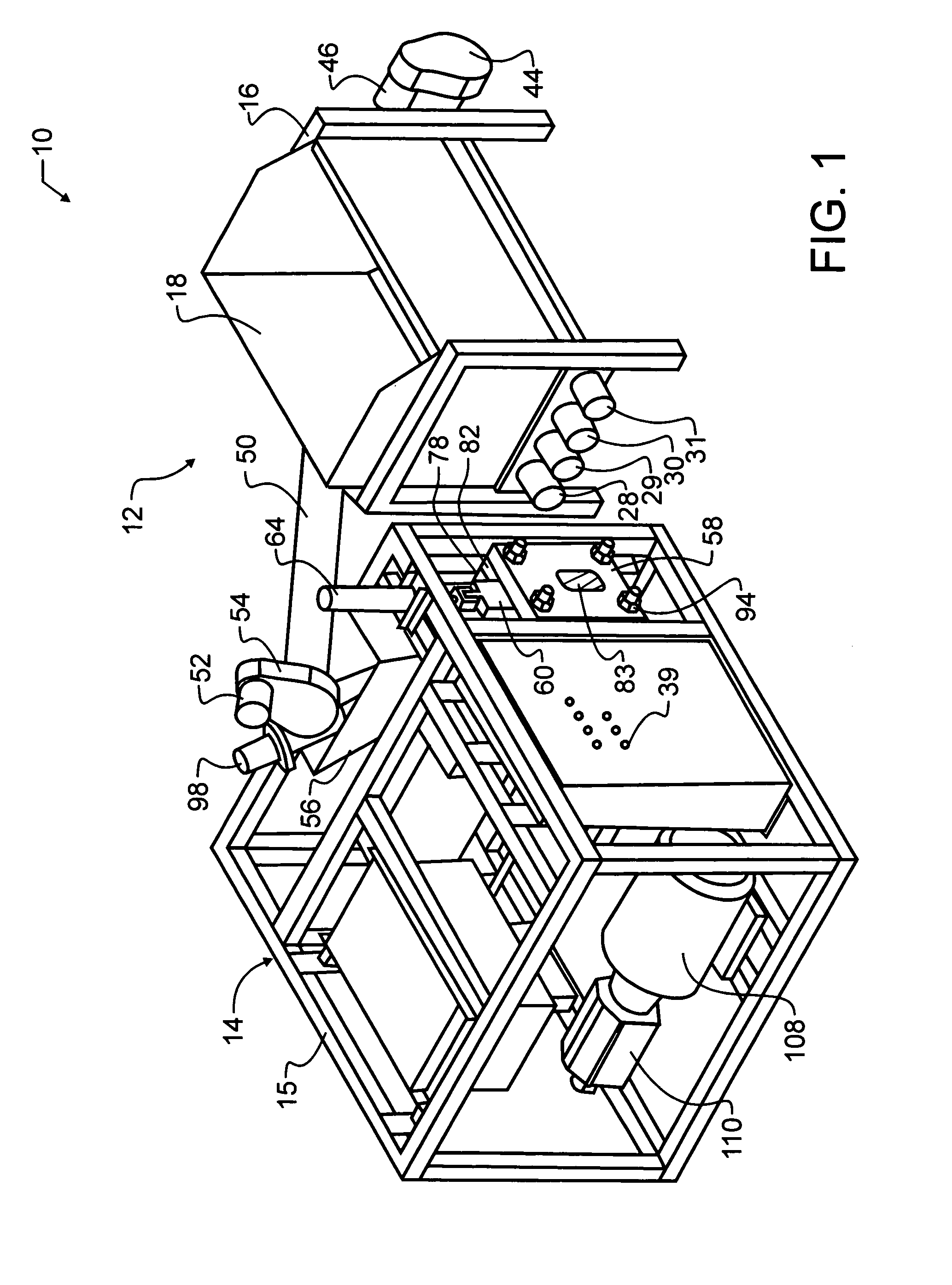
[0033]Manifested in the preferred embodiment, the present invention provides a compacting apparatus indicated generally at 10. Compacting apparatus 10 includes a supply hopper unit 12 and a compactor unit 14. The supply hopper unit 12 has a frame 16 that carries a supply bin 18. Supply bin 18 has an open top in order to receive scrap product such as metal shavings entrained with fluids such as cutting fluids. While the preferred embodiment has been optimized for use specifically with metal shavings and similar metal scrap produced during metal machining, those skilled in the art will recognize that the teachings provided herein could be applied to other scrap material as well, provided adequate consideration is given to the characteristics of such other material.

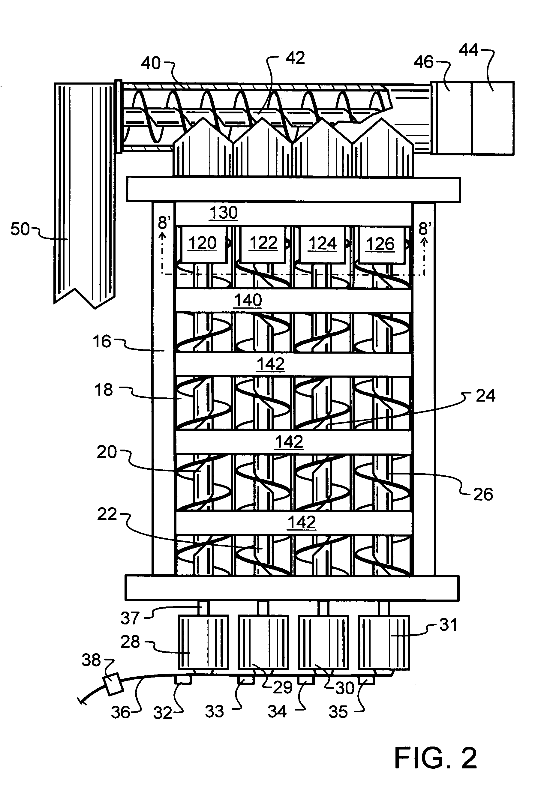
[0034]The bottom of the supply bin 18 is comprised of a plurality of spaced apart, parallel grinding augers, as visible in FIG. 2. Augers 20,22,24 and 26 are mounted to the frame 16 at the lower end thereof. Each auger is dr...


PUM


Abstract

A machining waste metal recycling machine has an in-feed hopper. The hopper uses paired augers to move the waste metal through the hopper to a cutting and transporting auger. The hopper augers are powered independently from each other, and may be individually reversed or reversed as a group to clear jams. In the event a jam is not cleared through one or more reversal cycles, the remaining augers may be operated to clear the hopper, thereby avoiding the need for manual unloading. Within the hopper are one or more shear bars that are provided to sever bunches or bundles of machining waste and thereby clear tangles which might otherwise jam the augers. The cutting and transporting augers ultimately feed a reciprocating compactor having a movable gate with one or more grooves for controlled drainage of machining oil and other liquid, as the machining waste metal is compressed into pellets.

Description

BACKGROUND OF THE INVENTION[0001]1. Field of the Invention[0002]This invention pertains generally to presses, and more particularly to an apparatus which compacts various machining wastes into slugs through reciprocating motion, while providing drainage of machining oil and other liquid through or along a movable pressure surface. In a most preferred embodiment, novel hopper augers are powered independently from each other, and are cooperative with perpendicular shear bars which serve to sever bunches or bundles of machining waste.[0003]2. Description of the Related Art[0004]Modern man has distinguished himself from other creatures by an ability to make and use a very wide variety of tools and machines. Almost without regard to the type or ultimate purpose of a machine, one or more metals or alloys will be used in fabrication. These metals may in many cases form one or more parts of the machine, but may also or instead form one of the various tools that are used in the formation of ...

Claims


Application Information

Patent Timeline
Patent Type & Authority Patents(United States)
IPC IPC(8): B30B9/02B02C19/22
CPCB02C19/22B30B9/047B30B9/327B30B9/3039B30B9/3078B30B9/067B02C2018/164Y10S100/906
Inventor RALICKI, DANIEL J.
Owner RALICKI DANIEL J
Why Eureka
Try Eureka