Wavelength tunable surface plasmon resonance sensor

a plasmon resonance and surface plasmon technology, applied in the field ofwavelength tunable surface plasmon resonance sensor, can solve the problems of sharp attenuation of the intensity of the reflected beam, experimentally difficult to maintain a very thin and constant thickness air gap, and these optical configurations have several practical limitations. , to achieve the effect of low sample volume, high sensitivity and high time resolution

Inactive Publication Date: 2006-04-18
UNIV OF WASHINGTON
View PDF15 Cites 137 Cited by
  • Summary
  • Abstract
  • Description
  • Claims
  • Application Information

AI Technical Summary

Benefits of technology

[0037]The SPR sensing and imaging methods and devices of the present invention are broadly applicable for detecting and characterizing virtually any material capable of changing the refractive index. In particular, the present methods are particularly useful for detecting chemical species including, but not limited to, biological polymers, such as proteins, peptides, oligonucelotides, glycoproteins, DNA, RNA, polysaccharides, and lipids and aggregates thereof. An advantage of the present methods and devices is that they provide sensitive detection methods which do not require pre-detection chemical labeling processes which are time consuming, costly and may substantially affect the chemical and / or physical properties of the labeled chemical species. Other advantages of the present sensing and imaging methods is that they provide very high time resolution, high sensitivity up to about 100 fM and require very low sample volumes.
[0038]The present invention provides methods and devices broadly applicable to any measurement technique or other processes which involves the formation of SPs. Particularly, wavelength tunability of the devices of the present invention provides efficient SP excitation. For example, wavelength tunable SP devices of the present invention may be used for effective excitation of photoluminescent materials in the SPR probe region. In an exemplary embodiment, devices of the present invention are used to generate SPs capable of exciting fluorescent or phosphorescent transitions of chemical species in the probe region, particularly in chemical species bound to the probe region. These devices may include a second detector positioned in optical communication with such fluorescent materials, which is capable of quantifying the intensity of SP induced fluorescence. Alternatively, wavelength tunable SP devices of the present invention may provide a means of delivering energy to materials in a reaction region to induce chemical or physical changes in the material.

Problems solved by technology

A drawback of the Otto SPR configuration is that it is experimentally difficult to maintain a very thin and constant thickness air gap.
Satisfaction of the resonance condition results in a sharp attenuation in the intensity of the reflected beam caused by a conversion of radiant energy of the incident beam into SPs at the interface between the thin metal film and the lower refractive index layer.
Despite the demonstrated effectiveness of angle modulation SPR techniques, theses optical configurations have several practical limitations.
First, angle modulation optical configurations require use of complicated optical component rotation assemblies for selectably adjusting the angle of incidence of the incident beam.
Optical configurations requiring use of such complex rotation assemblies are undesirable because they are costly, spatially restrictive and require frequent maintenance and realignment.
Second, use of complex optical component rotation assembles increases an instrument's sensitivity to optical misalignment caused by vibration and variations in ambient temperature and pressure.
Finally, use of coherent light sources, such as lasers, in angle modulation SPR techniques results in unwanted optical interference of reflected beam components.
Such optical interference is undesirable because it results in fringe patterns, which substantially degrades the optical quality of images obtained by SPR techniques.
Other regions of the probe area, in contrast, may comprise absorbed or bound materials having refractive indices which do not satisfy the SP resonance condition and do not result in efficient SP formation.
Although the authors report that SPR image quality may be optimized by selection of an interference filter having the appropriate transmission characteristics, the disclosed methods require time consuming, iterative image quality adjustment by manual removal and insertion of different interference filters.
Moreover, removal and insertion of optical interference filters requires repeated alignment of the excitation and detection optical arrangements.
In addition, the teaching of the reference is limited to optical configurations providing discrete detection wavelength selection and does not provide the ability to tune the excitation or detection wavelength over a continuous range of values.
Finally, the methods disclosed expose the sample to significant intensities of light having wavelengths not detected by the CCD camera, which do not contribute to SPR image formation and may damage materials in the probe region.

Method used


Image

  • Wavelength tunable surface plasmon resonance sensor
  • Wavelength tunable surface plasmon resonance sensor
  • Wavelength tunable surface plasmon resonance sensor

Examples


example 1

Characterization of an Exemplary SPR Sensor

[0083]The ability of SPR sensors of the present invention to sense changes in the refractive index of a probe region was verified by experimental and computational studies. Specifically, it is a goal of the present invention to provide SPR sensors capable of sensitively detection and characterization changes in the refractive index of a probe region. Further, it is a goal of the present invention to SPR sensors providing a large dynamic range, which are capable of probing materials having a wide range of refractive indices.

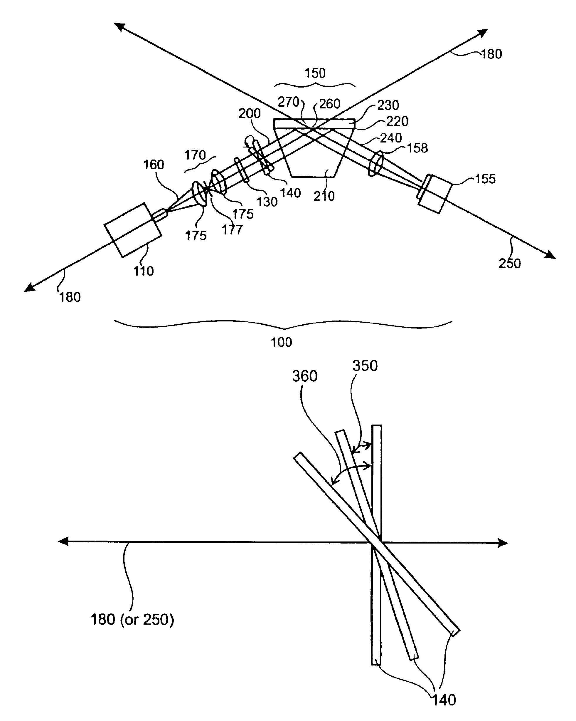
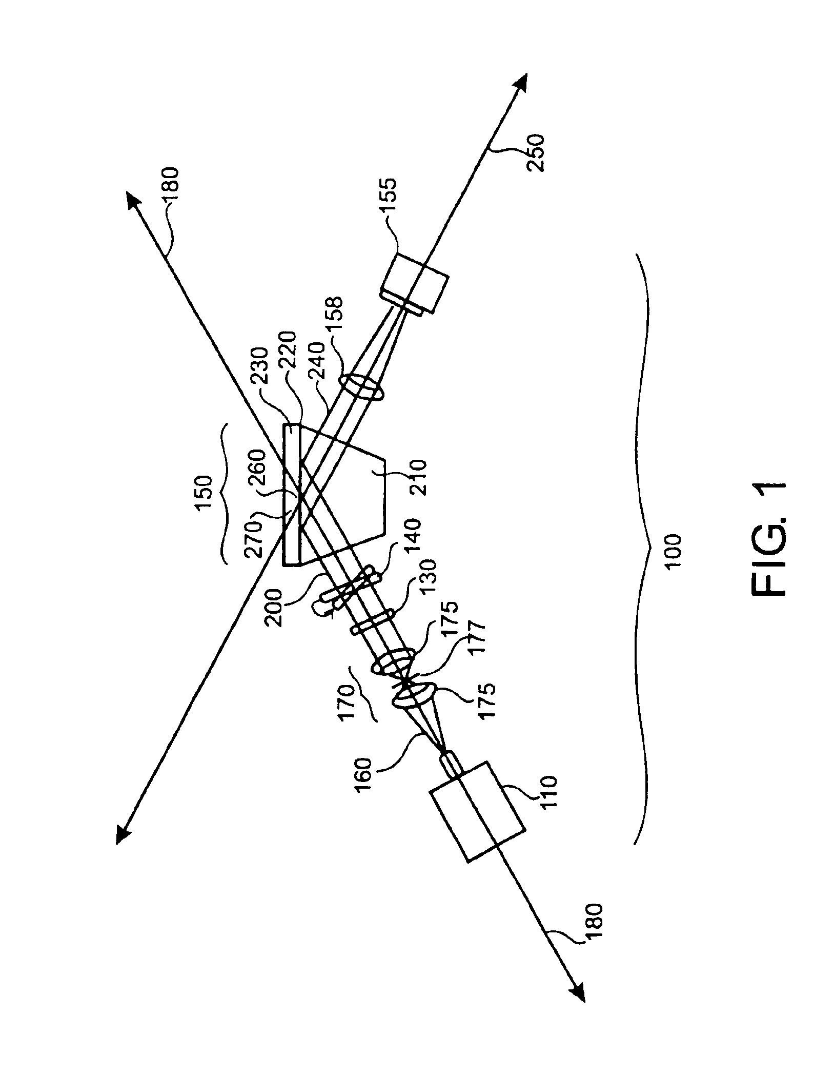
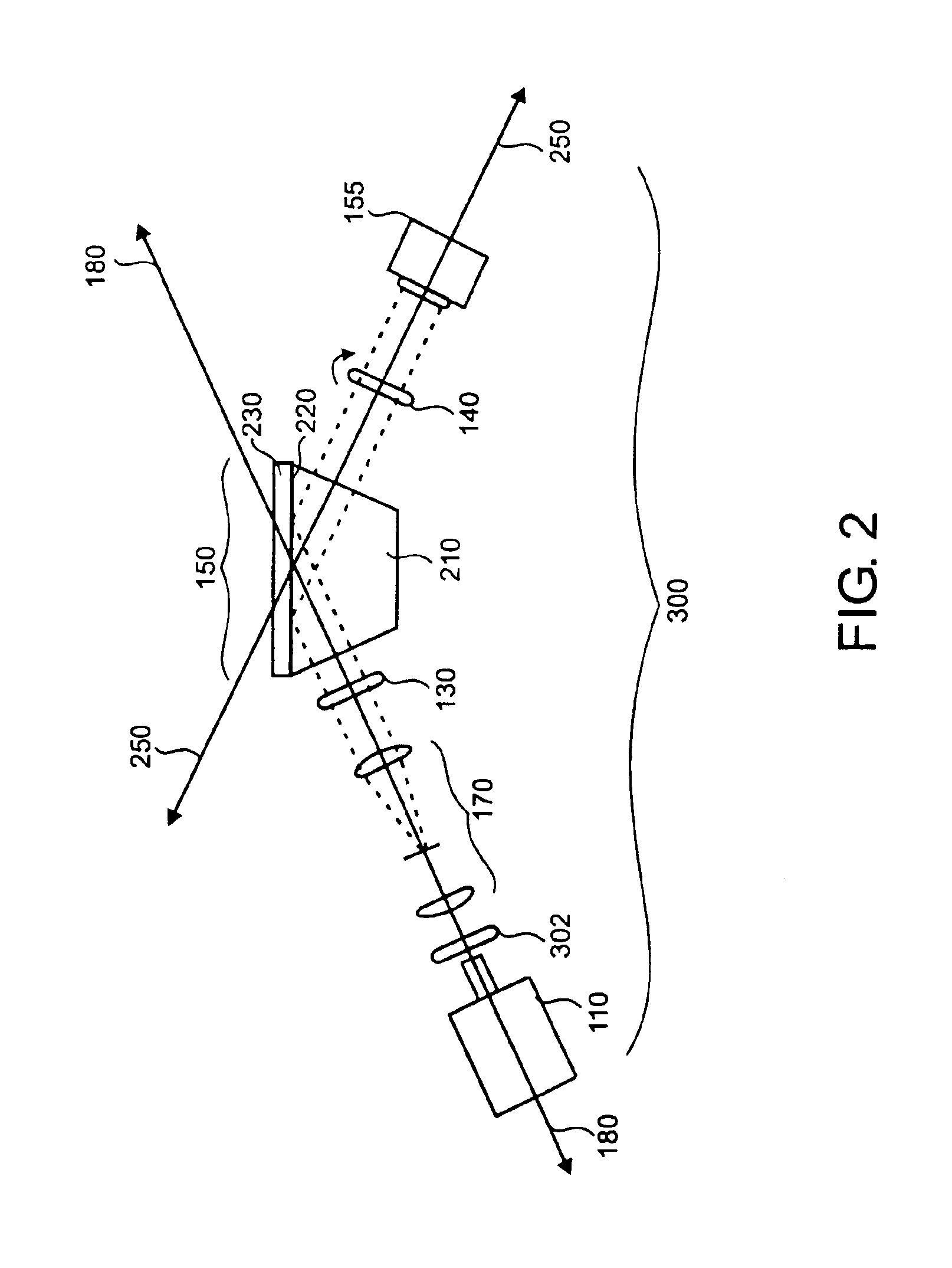
[0084]To achieve the aforementioned goals, detection sensitivities and dynamic ranges of an exemplary SPR sensor were computationally modeled and evaluated by monitoring the refractive indices of low concentration sucrose solutions. The exemplary SPR sensor 500 employed in these studies is based on the Kretschmann configuration and is shown in FIG. 5. The polychromatic light source is a 150 W quartz halogen lamp 510 (Dola...

example 2

SPR Images of Thiol Patterns and Protein Bovine Serum Albumin on Gold Surfaces

[0092]To assess the sensitivity and spatial resolution of SPR imaging devices of the present invention, SPR images of thiol patterns were generated by an exemplary SPR sensor. Thiol patterns on a gold surface (comprising approximately 1 nm Cr and approximately 45 nm Au electron beam deposited onto standard microscope slide from Fisher Scientific) was made using a polydimethylsiloxane (PDMS) stamping protocol. The protocol employed was optimized to minimize transfer of material from the PDMS stamp to the surface and to produce one monolayer of thiol on the surface. All images were taken with p-polarized light. FIG. 12 shows a series of images taken of a thiol and water pattern with an optical interference filter positioned a several different tilt angles. FIG. 12A corresponds to a center wavelength of 857 nm, FIG. 12B corresponds to a center wavelength of 852 nm, FIG. 12C corresponds to a center wavelength ...


PUM

PropertyMeasurementUnit
center wavelengthaaaaaaaaaa
tilt angleaaaaaaaaaa
decay lengthaaaaaaaaaa

Abstract

This invention provides methods, devices and device components for sensing, imaging and characterizing changes in the composition of a probe region. More particularly, the present invention provides methods and devices for detecting changes in the refractive index of a probe region positioned adjacent to a sensing surface, preferably a sensing surface comprising a thin conducting film supporting surface plasmon formation. In addition, the present invention provides methods and device for generating surface plasmons in a probe region and characterizing the composition of the probe region by generating one or more surface plasmon resonances curves and/or surface plasmon resonance images of the probe region.

Description

CROSS-REFERENCE TO RELATED APPLICATIONS[0001]This application claims priority under 35 U.S.C. 119(e) to provisional patent application 60 / 421,917, filed Oct. 28, 2002, which is hereby incorporated by reference in its entirety to the extent not inconsistent with the disclosure herein.STATEMENT REGARDING FEDERALLY SPONSORED RESEARCH OR DEVELOPMENT[0002]The work was funded through a grant by the United States government under NIDCR grant 1UO1 DE14971-01.BACKGROUND OF THE INVENTION[0003]Surface plasmon resonance (SPR) microscopy is a technique that uses excitation of surface plasmons (SPs) to detect chemical and physical changes in a probed region adjacent to a sensing surface. A variety of sensors based on SPR techniques have been developed which provide a sensitive means of characterizing the thickness and index of refraction of ultrathin films occurring at the surface of a thin metal film. In recent years, SP sensors have been used extensively to characterize chemical and physical pr...

Claims


Application Information

Patent Timeline
Patent Type & Authority Patents(United States)
IPC IPC(8): G01N21/55
CPCG01N21/553G01N21/648
Inventor YAGER, PAULFU, ELAIN S.
Owner UNIV OF WASHINGTON
Why Eureka
Try Eureka