Steam methane reforming method

a technology of steam methane and reforming method, which is applied in the direction of hydrogen sulfides, sulfur compounds, separation processes, etc., can solve the problems that olefins cannot be tolerated, and achieve the effects of reducing fuel consumption, reducing the total product synthesis gas and hydrogen production rate, and increasing the mole of synthesis gas product stream

Active Publication Date: 2006-05-02
PRAXAIR TECH INC
View PDF8 Cites 127 Cited by
  • Summary
  • Abstract
  • Description
  • Claims
  • Application Information

AI Technical Summary

Benefits of technology

[0028]In the foregoing two aspects of the present invention during both of the catalytic reactions, the steam methane reformer can be operated at a firing rate that remains substantially unchanged. As a result, the additional hydrogen produced during the catalytic reaction of the oxygen, steam, hydrocarbons and sulfur compounds increases the moles of synthesis gas product stream and the hydrogen production rate over that produced when the hydrogen, hydrocarbons and sulfur compounds are catalytically reacted without adding oxygen. In an alternative operation, during the catalytic reaction of the oxygen, steam, hydrocarbons and sulfur compounds, the steam methane reformer is operated at a lower firing rate than during the catalytic reaction of the hydrogen, hydrocarbons and sulfur compounds. This allows for reduced fuel usage to the steam methane reformer and with of course, a lower total product synthesis gas and hydrogen production rate than when the steam methane reformer is operated at constant firing. The steam production rate can be equivalent to that obtained during the hydrogenation mode....

Problems solved by technology

In this regard, although higher order hydrocarbons might be tolerated ...

Method used


Image

  • Steam methane reforming method
  • Steam methane reforming method
  • Steam methane reforming method

Examples


Embodiment Construction

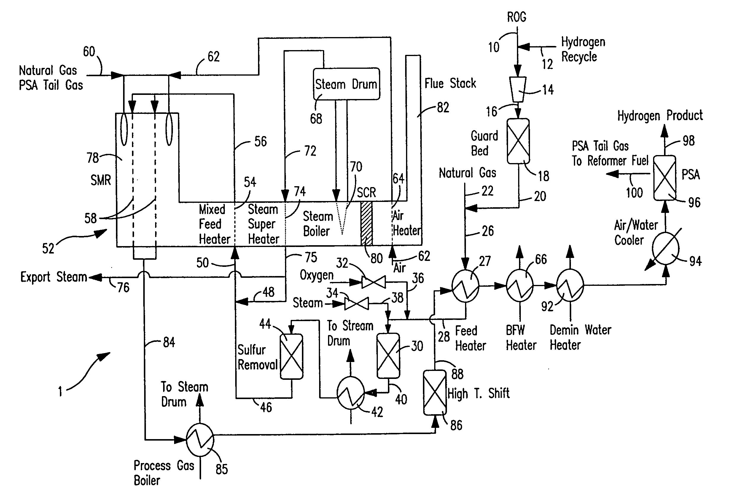
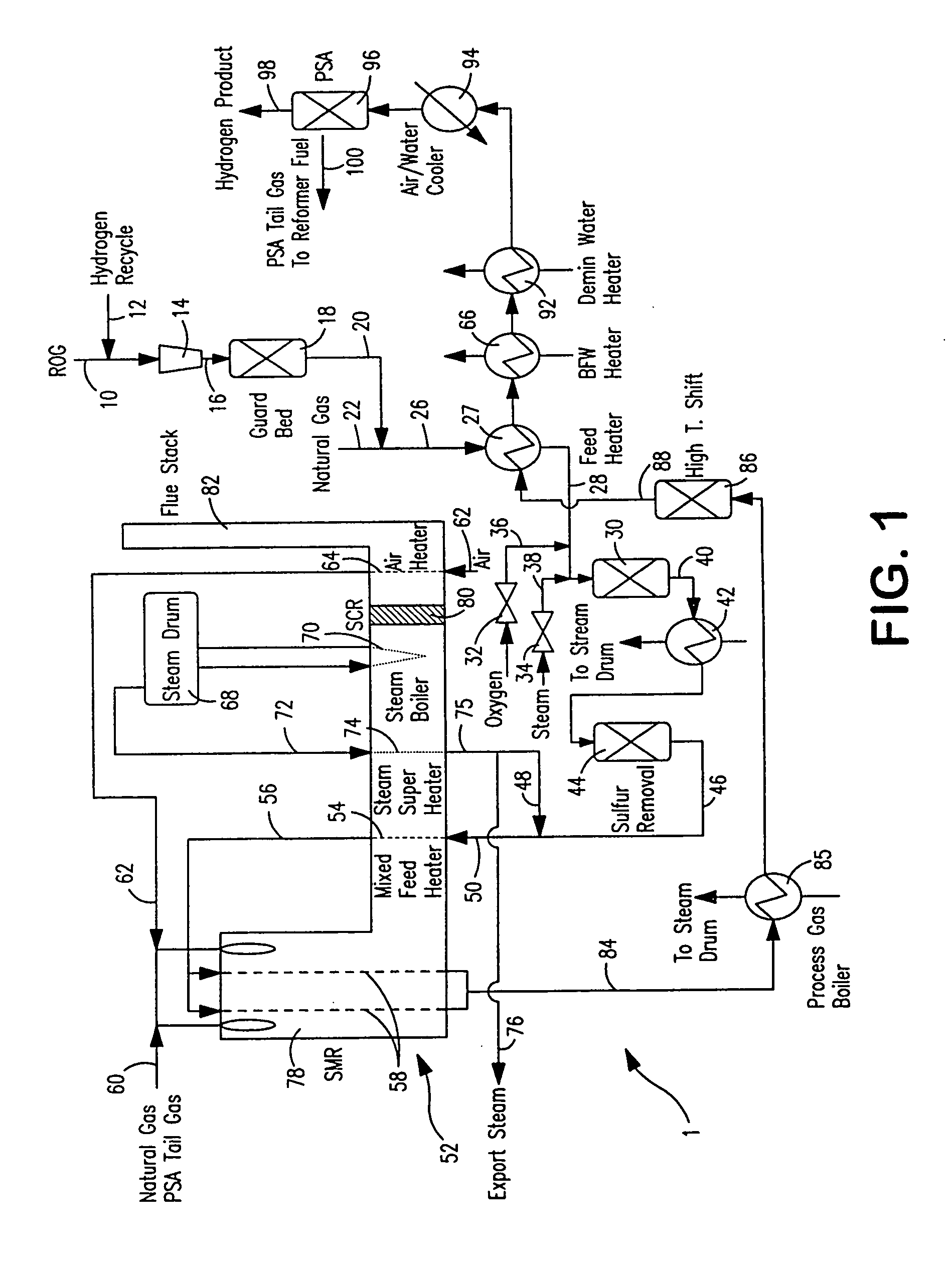
[0038]With reference to FIG. 1, an apparatus 1 is illustrated for carrying a method in accordance with the present invention. Apparatus 1 illustrates the integration of the present invention into a conventional steam methane reforming process to treat refinery off-gases and / or natural gas. In this regard, although the refinery off-gases in FIG. 1 are used in such process to partially replace natural gas as feed to reformer, it is understood that the present invention can be conducted with the object of solely reforming such refinery off-gases or any other gas stream as described above in which steam methane reforming would be problematical due to its hydrocarbon content or have as its sole object the refining of natural gas or other gas stream having a hydrocarbon content that is completely compatible with conventional steam methane reforming techniques. Other streams to be treated may or may not have an objectionable sulfur content to be removed.

[0039]In apparatus 1, a refinery off...


PUM


Abstract

A steam methane reforming method in which a feed stream is treated in a reactor containing a catalyst that is capable of promoting both hydrogenation and partial oxidation reactions. The reactor is either operated in a catalytic hydrogenation mode to convert olefins into saturated hydrocarbons and/or to chemically reduce sulfur species to hydrogen sulfide or a catalytic oxidative mode utilizing oxygen and steam to prereform the feed and thus, increase the hydrogen content of a synthesis gas produced by a steam methane reformer. The method is applicable to the treatment of feed streams containing at least 15% by volume of hydrocarbons with two or more carbon atoms and/or 3% by volume of olefins, such as a refinery off-gas. In such case, the catalytic oxidative mode is conducted with a steam to carbon ratio of less than 0.5, an oxygen to carbon ratio of less than 0.25 and a reaction temperature of between about 500° C. and about 860° C. to limit the feed to the steam methane reformer to volumetric dry concentrations of less than about 0.5% for the olefins and less than about 10% for alkanes with two or more carbon atoms.

Description

RELATED APPLICATIONS[0001]The present application is a continuation-in-part of U.S. patent application Ser. No. 10 / 990,485, filed Nov. 18, 2004, now abandoned.FIELD OF THE INVENTION[0002]The present invention relates to a steam methane reforming method in which a hydrocarbon feed stream containing methane and / or hydrocarbons with two or more carbon atoms is converted into an intermediate product within a catalytic reactor and the intermediate product is subsequently reformed in a steam methane reformer to in turn produce a synthesis gas product. More particularly, the present invention relates to such a method in which the catalytic reactor is capable of operating in either a mode involving the hydrogenation of hydrocarbons and sulfur compounds into saturated hydrocarbons and hydrogen sulfide or an alternative mode involving the use of oxygen to produce additional hydrogen.BACKGROUND OF THE INVENTION[0003]In a typical steam methane reformer operation for the production of hydrogen, ...

Claims


Application Information

Patent Timeline
IPC IPC(8): C01B3/00C01B17/16C01B3/32
CPCC01B3/382C01B3/384C01B3/48C01B3/56C01B17/0408C01B2203/0827Y02E60/324C01B2203/0894C01B2203/1023C01B2203/1047C01B2203/1241C01B2203/1258C01B2203/127C01B2203/142C01B2203/143C01B2203/82C01B2203/0233C01B2203/0244C01B2203/0283C01B2203/043C01B2203/047C01B2203/0475C01B2203/0816C01B2203/0822C01B2203/0844Y02P20/10Y02E60/32
Inventor DRNEVICH, RAYMOND FRANCISPAPAVASSILIOU, VASILIS
Owner PRAXAIR TECH INC
Why Eureka
Try Eureka