Mass spectrometer and method of mass spectrometry

a mass spectrometer and mass spectrometry technology, applied in mass spectrometers, particle separator tubes, separation processes, etc., can solve the problems of inaccurate mass assignment, low mass spectral intensity, and certain dead-time of detectors, so as to minimise any change in resolution, reduce the effect of mass position and spectral skew, and alter the efficiency of ion transmission efficiency

Inactive Publication Date: 2006-05-02
MICROMASS UK LTD
View PDF37 Cites 38 Cited by
  • Summary
  • Abstract
  • Description
  • Claims
  • Application Information

AI Technical Summary

Benefits of technology

[0030]However, z-focusing is preferred to other ways of altering the ion transmission efficiency since it has been found to minimise any change

Problems solved by technology

However, such ion detectors exhibit a certain dead-time following an ion impact during which time the detector cannot respond to another ion impact.
If during acquisition of a mass spectrum ions arrive during the detector dead-time then they will consequently fail to be detected, and this will have a distorting effect on the resultant mass spectra.
At high ion currents multiple ion arrivals cause counts to be missed resulting in mass spectral peaks with lower intensity than expected and inaccurate mass assignment.
However, software correction techniques are only able to provide a limited d

Method used


Image

  • Mass spectrometer and method of mass spectrometry
  • Mass spectrometer and method of mass spectrometry
  • Mass spectrometer and method of mass spectrometry

Examples


Embodiment Construction

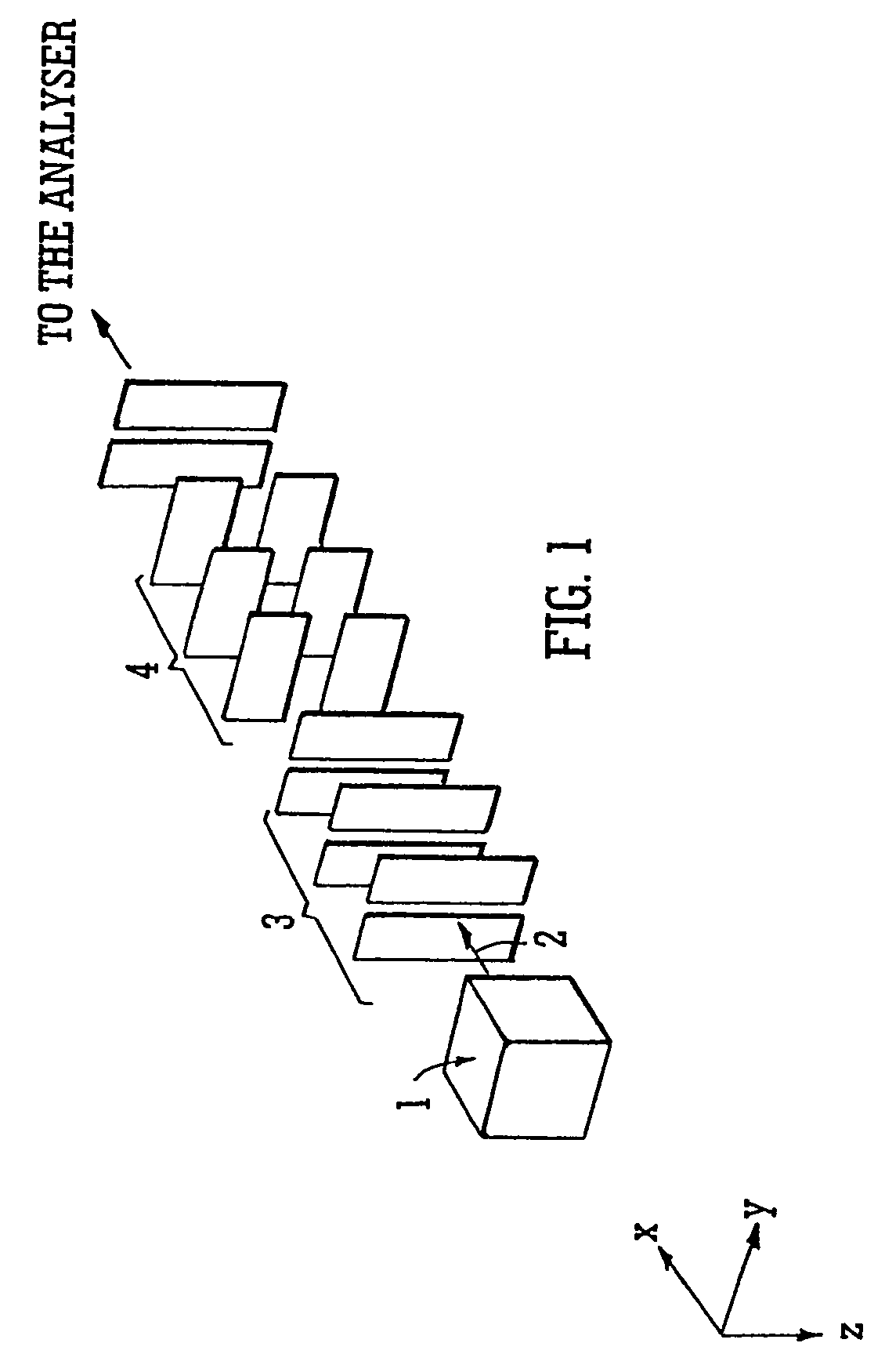
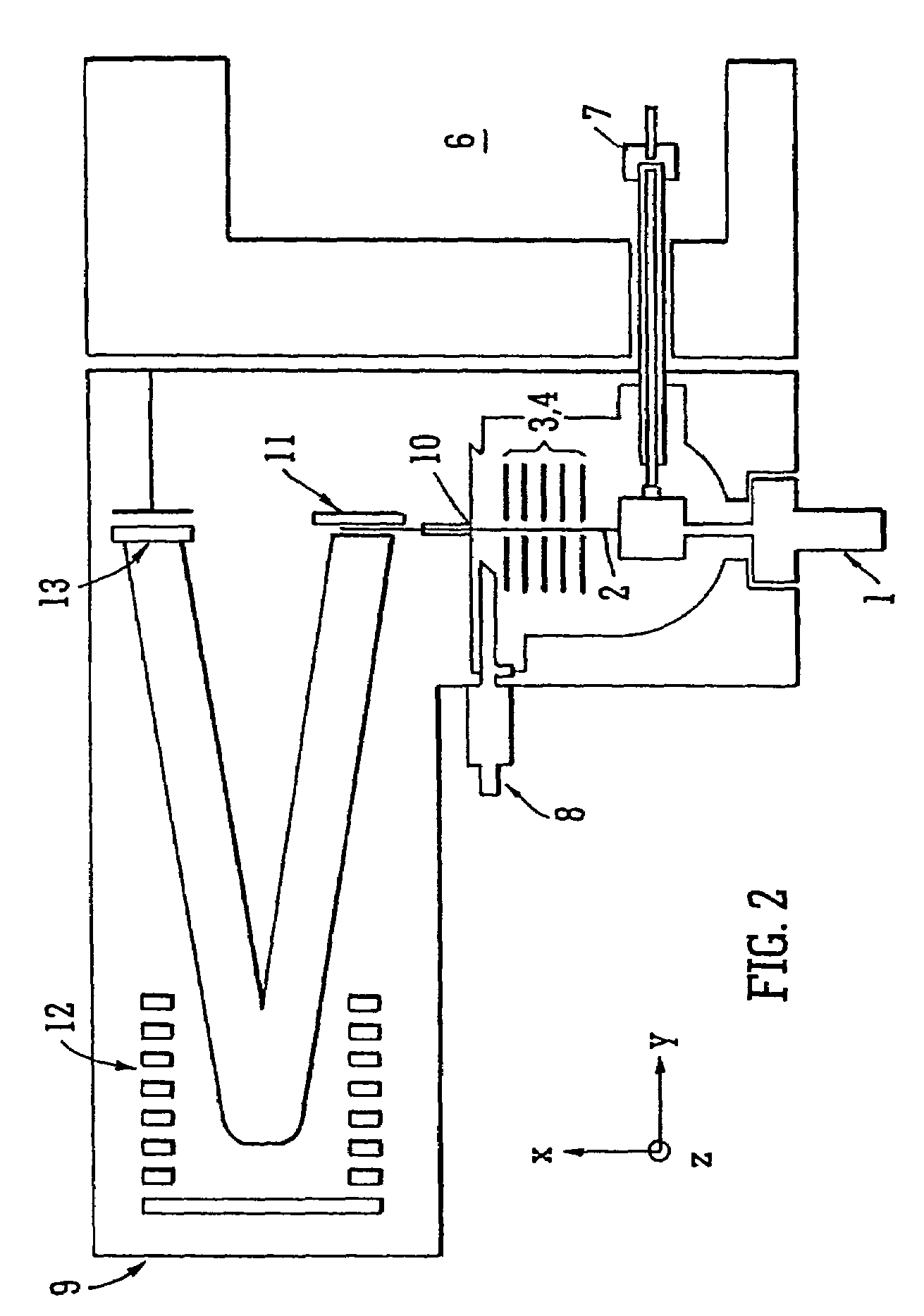
[0148]Various embodiments of the present invention will now be described. FIG. 1 shows an ion source 1, preferably an Electron Impact or Chemical Ionisation ion source. An ion beam 2 emitted from the ion source 1 travels along an axis referred to hereinafter as the x-axis. The ions in the beam 2 may be focused / collimated in a y-direction orthogonal to the x-axis by a y-lens 3. A z-lens 4 is preferably provided downstream of the y-lens 3. The z-lens 4 may be arranged to deflect or focus the ions in the z-direction which is perpendicular to both the y-direction and to the x-axis. The z-direction is also orthogonal to the plane of a subsequent mass analyser 9 (see FIGS. 2 and 3).

[0149]The z-lens 4 may comprise a number of electrodes, and according to a preferred embodiment comprises an Einzel lens wherein the front and rear electrodes are maintained in use at substantially the same fixed DC voltage, and the DC voltage applied to an intermediate electrode may be varied to alter the degr...


PUM


Abstract

A mass spectrometer is disclosed wherein a z-lens upstream of an orthogonal acceleration Time of Flight mass analyser is repeatedly switched between a first mode wherein ions are transmitted to the mass analyser for subsequent mass analysis with a relatively high transmission and a second mode wherein ions are transmitted with a relatively low transmission. If it is determined that mass spectral data obtained when the mass analyser is in the first mode is suffering from saturation, then suitably scaled mass spectral data obtained when the mass analyser is in the second mode is used instead. If the saturation is severe then the mass spectral data obtained in the first mode may be replaced in its entirety with mass spectral data obtained in the second mode.

Description

CROSS-REFERENCE TO RELATED APPLICATIONS[0001]The present application constitutes a continuation-in-part of U.S. patent application Ser. No. 09 / 823,992 filed Apr. 3, 2001, now U.S. Pat. No. 6,878,929.BACKGROUND OF THE INVENTION[0002]1. Field of the Invention[0003]The present invention relates to a mass spectrometer and method of mass spectrometry.[0004]2. Discussion of the Prior Art[0005]Time of Flight mass analysers are well known wherein packets of ions are ejected by an electrode such as a pusher electrode into a field free drift region with essentially the same kinetic energy. In the drift region ions with different mass to charge ratios travel with different velocities and therefore arrive at an ion detector disposed at the exit of the drift region at different times. Measurement of the ion transit time therefore determines the mass to charge ratio of that particular ion.[0006]One of the most commonly employed ion detectors in Time of Flight mass spectrometers is a single ion co...

Claims


Application Information

Patent Timeline
IPC IPC(8): H01J49/40G01K1/08G01N27/62H01J49/26
CPCH01J49/067H01J49/0027
Inventor BATEMAN, ROBERT HAROLDGREEN, MARTINJACKSON, MICHAEL
Owner MICROMASS UK LTD
Why Eureka
Try Eureka