Energy conditioning circuit assembly

a circuit assembly and energy conditioning technology, applied in the direction of high frequency circuit adaptation, printed circuit non-printed electric components association, circuit details of semiconductor/solid-state devices, etc., can solve the problems of requiring extensive repair and/or replacement at great cost, straying electrical energy, and affecting the operation of electronic equipment, etc., to achieve the effect of improving shielding

Inactive Publication Date: 2006-05-09
X2Y ATTENUATORS L L C
View PDF468 Cites 62 Cited by
  • Summary
  • Abstract
  • Description
  • Claims
  • Application Information

AI Technical Summary

Benefits of technology

[0016]One embodiment comprises a carrier that also provides the added benefit of improved shielding from elec

Problems solved by technology

The majority of electronic equipment produced presently, and in particular computers, communication systems, military surveillance equipment, stereo and home entertainment equipment, televisions and other appliances include miniaturized components to perform new high speed functions and electrical interconnections which according to the materials from which they are made or their mere size are very susceptible to stray electrical energy created by electromagnetic interference or voltage transients occurring on electrical lines.
Voltage transients can severely damage or destroy such micro-electronic components or contacts thereby rendering the electronic equipment inoperative, and requiring extensive repair and/or replacement at great cost.
While the above referenced electronic components accomplish their respective tasks, usage of such components has been limited for a number of reasons.
First, the number of such components required continues to increase as applications, such as data buses, continue to grow.
Second, by their nature the electronic components referred to are delicate structures which do not handle physical stress well.
During the manufacture of ele

Method used


Image

  • Energy conditioning circuit assembly
  • Energy conditioning circuit assembly
  • Energy conditioning circuit assembly

Examples


Embodiment Construction

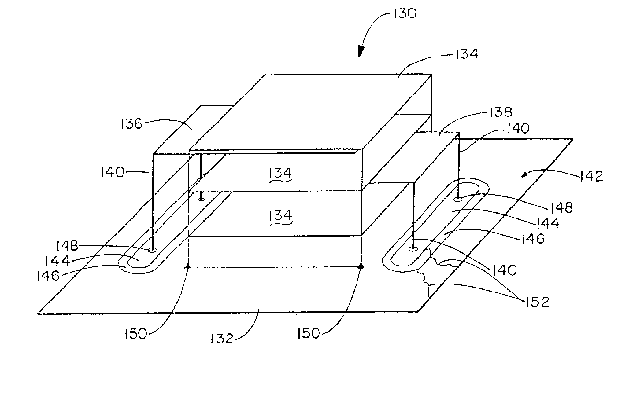
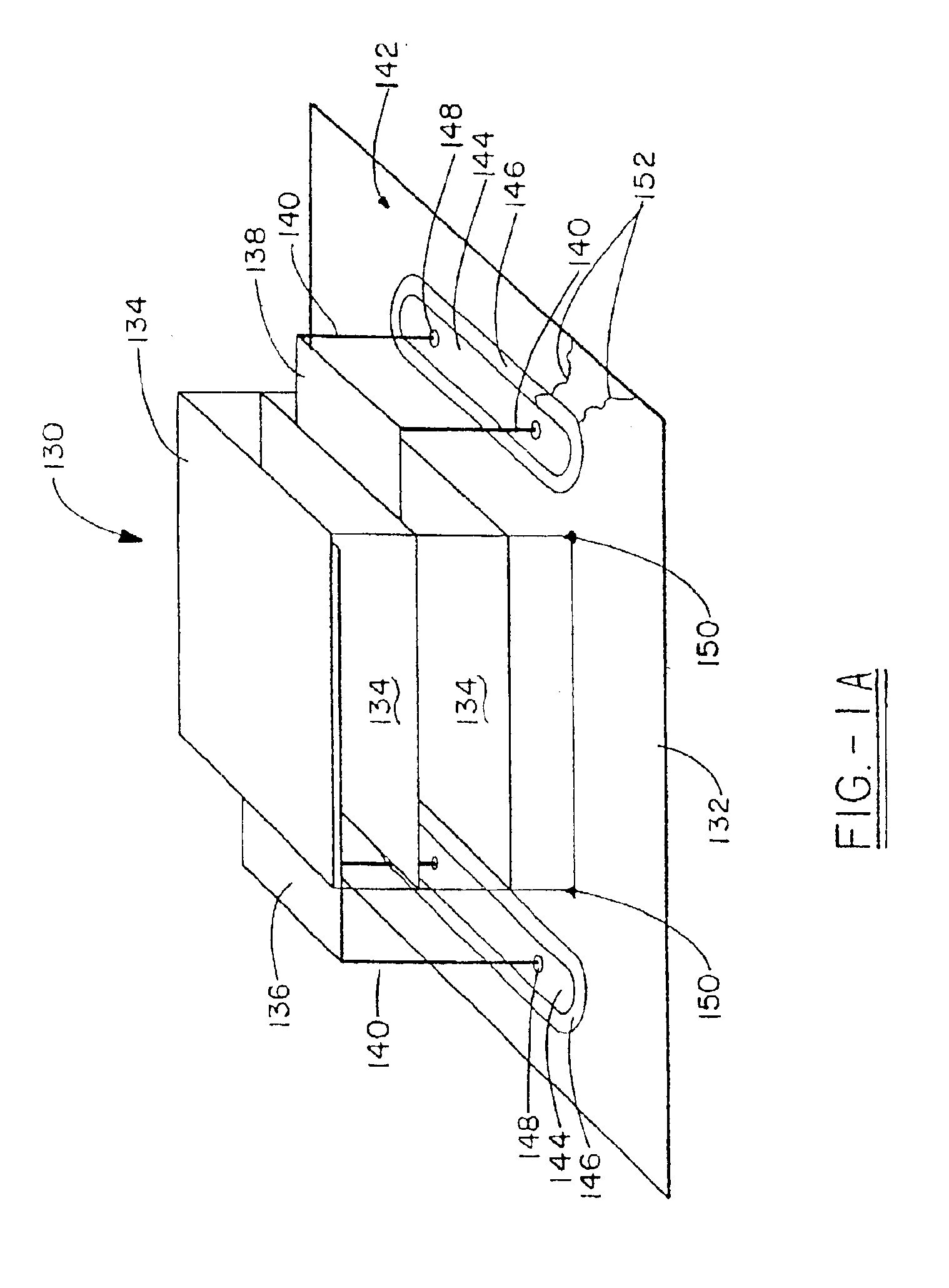
[0041]FIG. 1A shows the present invention in its simplest form. Component carrier 132 is shown coupled with a differential and common mode filter 130 having thru-hole leads 140 for electrical coupling to carrier 132. Differential and common mode filter 130 is disclosed in commonly owned U.S. Pat. No. 5,909,350 (Ser. No. 08 / 841,940); U.S. Pat. No. 6,097,581 (Ser. No. 09 / 008,769; and U.S. Pat. No. 6,018,448 (Ser. No. 09 / 056,379), incorporated herein by reference. Briefly, the structure of differential and common mode filter 130 will be described. Filter 130 consists of a first electrode 136 and a second electrode 138 which are separated by and electrically isolated from a plurality of ground layers 134 and each other by a dielectric medium. The particular architecture creates a line-to-line capacitor and two line-to-ground capacitors which provide for differential and common mode filtering and decoupling.

[0042]Because filter 130 is a somewhat fragile component, component carrier 132 p...


PUM


Abstract

The present invention is a component carrier (132) consisting of a plate of insulating material having a plurality of apertures (140) for accepting the leads of a thru-hole differential and common mode filter (130). Another embodiment consists of a surface mount component carrier (10) comprising a disk (16) of insulating material having a plurality of apertures (24). The same concept for the above described carrier is also incorporated into several alternate embodiments, either independently, embedded within electronic connectors. The overall configuration and electrical characteristics of the concepts underlying the present inventions are also described as an energy conditioning circuit assembly which encompasses the combination of differential and common mode filters and component carriers optimized for such filters. The various embodiments of component carriers provide increased physical support and protection to differential and common mode filters and substantially improve the electrical characteristics of the filters due to the increased shielding provided by the carriers. Embodiments of the carrier energy conditioning assembly include integrated circuit construction for a differential and common mode filter coupled to the power bus of an integrated circuit.

Description

[0001]This application is a continuation of copending U.S. patent application Ser. No. 09 / 999,787 filed Oct. 24, 2001, which is a continuation of U.S. patent application Ser. No. 09 / 561,283 filed Apr. 28, 2000, now U.S. No. 6,509,807, which is a continuation-in-part of application Ser. No. 09 / 600,530 which is a U.S. national stage application of international application PCT / US99 / 01040 filed Jan. 16, 1999, Application Ser. No. 09 / 561,283 is also a continuaton-in-part of U.S. patent application Ser. No. 09 / 286,812 filed Apr. 6, 1999, now abandoned, which is a continuation-in-part of U.S. patent application Ser. No. 09 / 056,436 filed Apr. 7, 1998, now abandoned, application Ser. No. 09 / 561,283 claims benefit of U.S. Provisional Application 60 / 131,386 filed Apr. 28, 1999, U.S. Provisional Application 60 / 135,542 filed May 24, 1999, U.S. Provisional Application 60 / 136,451 filed May 28, 1999, U.S. Provisional Application 60 / 139,182 filed Jun. 15, 1999, U.S. Provisional Application 60 / 146,9...

Claims


Application Information

Patent Timeline
IPC IPC(8): H04B3/28H01L23/50H01L23/552H01R13/719H03H1/00H05K1/02H05K1/14H05K1/16H05K1/18H05K3/34
CPCH01G2/065H01G4/232H01L23/50H01L23/552H01R13/719H03H1/0007H01L2924/0002H01L2924/09701H05K1/0237H05K1/141H05K1/162H05K1/18H05K1/181H05K3/3436H01L2924/00
Inventor ANTHONY, ANTHONY A.ANTHONY, WILLIAM M.
Owner X2Y ATTENUATORS L L C
Why Eureka
Try Eureka