Low resistance value resistor

Inactive Publication Date: 2006-05-09
KOA CORP
View PDF33 Cites 18 Cited by
  • Summary
  • Abstract
  • Description
  • Claims
  • Application Information

AI Technical Summary

Benefits of technology

[0014]According to the present invention, a portion of the resistor body removed by a trimming process extends along the path of current flow so that the direction of the current flow in the trimmed resistor body is hardly affected by the removal of the portion. That is, as shown in FIG. 7 of the conventional low resistance value resistor, laser trimming is applied at right angles to the current flow to produce cutouts 1300, so that the direction of the current flow in the trimmed resistor is altered considerably, because the current

Problems solved by technology

However, it is difficult to form a thick deposit on the resistor body by electroplating, and for this reason, uniformity of electric potential through the electrode is low, and the current path can not be stabilized, thereby making it difficult to manufacture low resistance value resistors of high precision.
Also, bonding between the metallic material constituting the resistor body and the electrode produced by electroplating is weak, and problems occur when it is necessary to bend the resi

Method used


Image

  • Low resistance value resistor
  • Low resistance value resistor
  • Low resistance value resistor

Examples


first embodiment

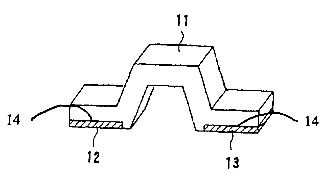
[0022]Preferred embodiments will be explained in the following with reference to the drawings. FIG. 1 shows an example of the structure of a low resistance value resistor in a As shown in the diagram, the resistor is provided with a metal strip members 12, 13 bonded to each end of the metal (base material) 11, serving as the resistor body, by means of (thermal) diffusion bonding and the like. In this example of the structure, the metal strip members 12, 13 are inlaid in the metal base 11, producing the so-called inlay cladding structure. Here, the base material preferably includes copper-nickel alloys, nichrome alloys or iron chromium alloys. The metal strip members having a thickness of about 50 to 200 μm are made of copper or nickel and are bonded to the base material by rolling and / or thermal diffusion bonding.

[0023]The low resistance value resistor has an extended length of about 20 mm or less, for example, width of about 5 mm, and the metal strip members are bonded so as to be...

second embodiment

[0031]Next, the low resistance value resistor will be explained.

[0032]FIG. 4 shows a low resistance value resistor 100 in the second embodiment, which is solder mounted to conductor patterns on a substrate base 150.

[0033]The resistor 100 is comprised by a metallic resistor body 110; electrodes 121, 122 serving as connecting terminals; and bonding electrodes 141, 142. The resistor 100 is constructed by two electrodes 121, 122 of a tetragonal shape and two bonding electrodes 141, 142 of a tetragonal shape, which are bonded to one resistor body 110 of a tetragonal shape, as shown in FIG. 4.

[0034]Voltage measurement using the low resistance value resistor 100 is carried out by connecting the conductor patterns of the substrate base 150 and the electrodes 121, 122, and connecting bonding-wires to the bonding electrodes 141, 142 by bonding means and the like so as to enable a voltage drop between the bonding electrodes 141, 142 to be measured. As shown in FIG. 4, preferable bonding positi...

third embodiment

[0050]A third embodiment will be explained with reference to FIG. 5.

[0051]FIG. 5 shows a resistor 500 in the third embodiment mounted on the conductor pattern of the substrate base 550. The resistor 500 is comprised by a resistor body 510 made of a metallic material and electrodes 521, 522 serving as the contact terminals.

[0052]To perform voltage measurements using the resistor 500, the conductor pattern on the substrate base 550 and the electrodes 521, 522 are connected, wires are connected to wire sites 542, 543, shown in FIG. 5, by wire bonding means, for example, and a voltage drop between the wire sites 542, 543 is measured. The width of the wire sites 542, 543 is ½ of the distance of the electrodes 521, 522, and the sites are formed where the locations are suitable for connecting wires. It should be noted that, in the above explanation, wire bonding was used as an example of obtaining a connection for measuring voltage drop therebetween, but a voltage drop can be measured with...


PUM


Abstract

The low resistance value resistor 11 has two electrodes 12,13 of metal strips having a high electrical conductivity. The metal strips are affixed on the resistor body by means of rolling and/or thermal diffusion bonding. A fused solder layer is formed on a surface of each electrode comprised by the metal strip. Thus, sufficient bonding strength and superior current distribution in the resistor body is obtained. Further, a portion of the resistor body is trimmed by removing a portion of the body material along a direction of current flow between the electrodes to adjust a resistance value. Thus, a precise resistor value and superior characteristics of temperature coefficient of resistance (TCR) can be obtained.

Description

CROSS REFERENCE TO RELATED APPLICATION[0001]This application is a continuation of Ser. No. 09 / 825,446, filed Apr. 4, 2001 now U.S. Pat. No. 6,794,985.BACKGROUND OF THE INVENTION[0002]1. Field of the Invention[0003]The present invention relates to a low resistance value resistor suitable for use in applications such as current detector and the like, and relates in particular to a resistor made of a resistive alloy and having an electrode placed at each end of the resistor body.[0004]2. Description of the Related Art[0005]Low resistance value resistors of a plate- or ribbon-shape having an electrode placed at each end of a metallic base material are widely used in applications such as current detector and the like because of their characteristics of good heat dissipation and high current carrying capacity. Metallic materials serving as a resistor body include, for example, copper-nickel alloys, nichrome alloys, iron-chromium alloys and manganese alloys, and an electrode is placed at e...

Claims


Application Information

Patent Timeline
IPC IPC(8): H01C1/12H01C1/144H01C17/242
CPCH01C17/242H01C1/144
Inventor NAKAMURA, KEISHITATUGUCHI, MIKIO
Owner KOA CORP
Why Eureka
Try Eureka