Chemical hydride hydrogen generation system and fuel cell stack incorporating a common heat transfer circuit

a technology of hydrogen generation system and fuel cell stack, which is applied in the direction of hydrogen production, electrochemical generators, chemistry apparatus and processes, etc., can solve the problems of increasing the overall system weight, each of these systems is either hazardous or bulky, and achieves the effect of effective heat transfer between them

Active Publication Date: 2006-05-16
HYDROGENICS CORP
View PDF19 Cites 16 Cited by
  • Summary
  • Abstract
  • Description
  • Claims
  • Application Information

AI Technical Summary

Benefits of technology

[0011]3) circulating a heat transfer fluid through the fuel cell stack and ...

Problems solved by technology

However, these fuel cells require external supply and storage devices for hydrogen.
However, each of these systems is either hazardous or bulky.
However, in such systems the stirring mechanism consumes energy, increases the overall system weight and reduces system efficiency.
Further, the noise generated in the stirring operation is undesirable.
In addition, the reaction rate is low, making the fuel unres...

Method used


Image

  • Chemical hydride hydrogen generation system and fuel cell stack incorporating a common heat transfer circuit
  • Chemical hydride hydrogen generation system and fuel cell stack incorporating a common heat transfer circuit
  • Chemical hydride hydrogen generation system and fuel cell stack incorporating a common heat transfer circuit

Examples


second embodiment

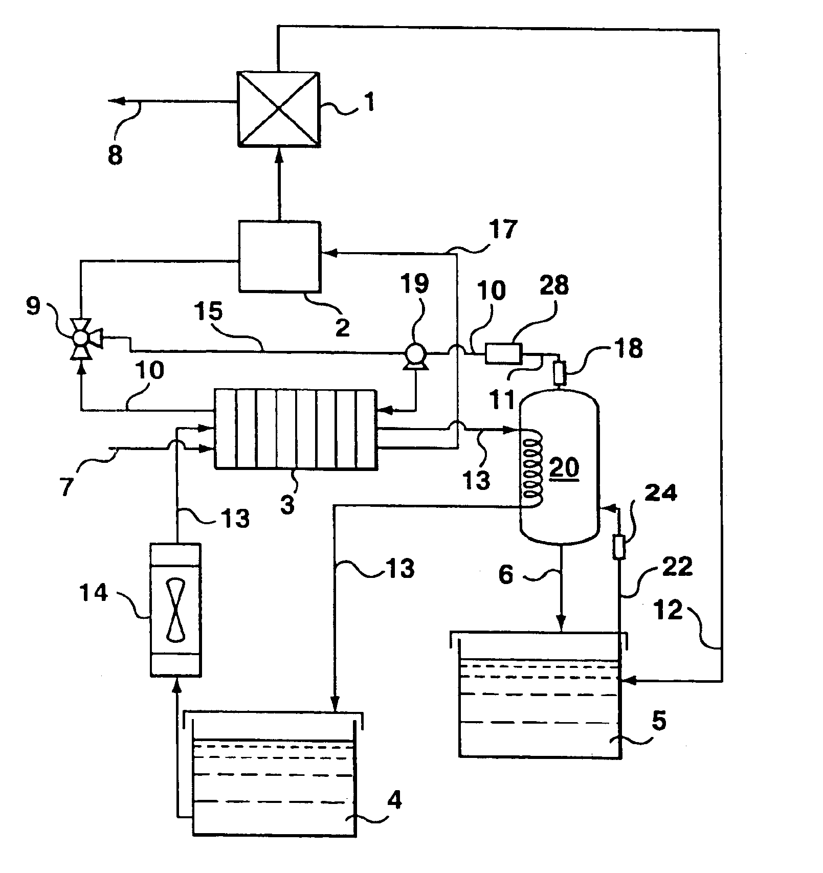
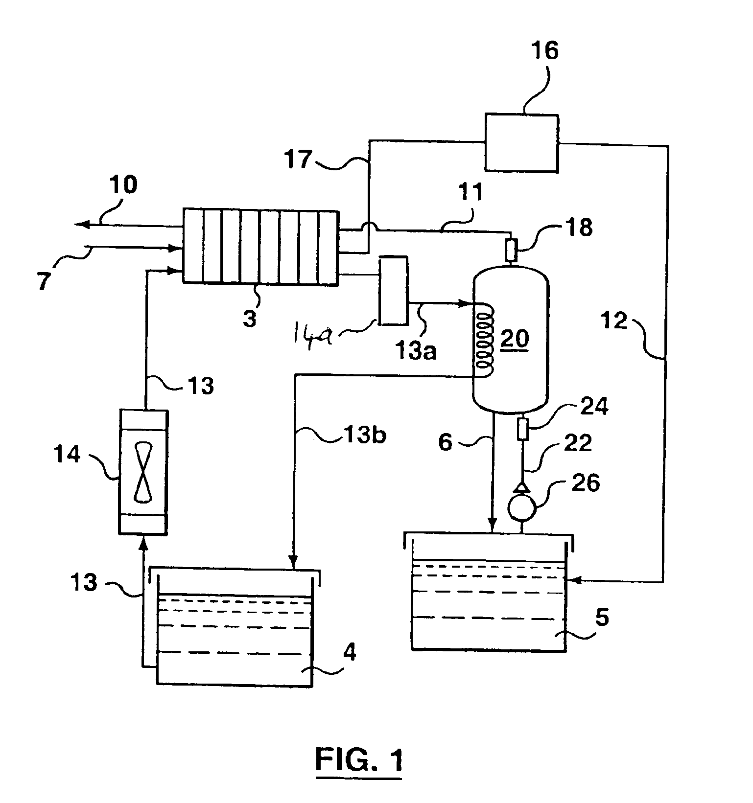
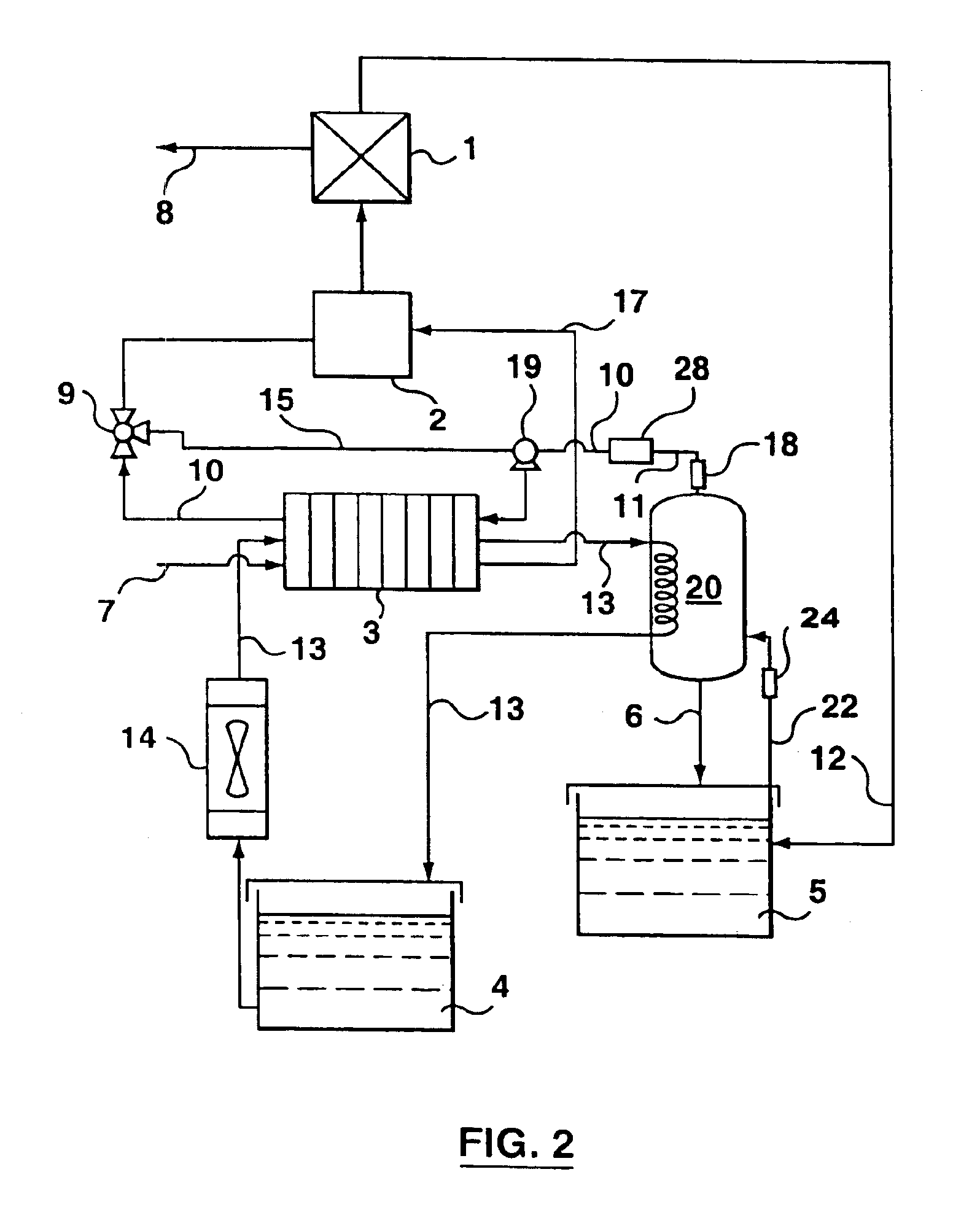
[0052]Now referring to FIG. 2, the present invention is shown. In this embodiment, similar components are indicated with same reference numbers. As can be seen in FIG. 2, the chemical hydride hydrogen generation system according to the present invention combines a hydrogen generation system and a fuel cell system. The hydrogen generation system generally includes a chemical hydride storage tank 5 and a reactor 20. The fuel cell includes a fuel cell stack 3 and some peripherals, namely a coolant storage tank 4, a heat exchanger 14, a catalytic burner 2 and a water recovery unit 1. In this embodiment, the present invention is also described using NaBH4 as an example of the chemical hydride used in the hydrogen generation system.

[0053]The hydrogen is generated in the reactor 20 in the same manner as that in the first embodiment. Likewise, the coolant loop is also identical to that in the first embodiment. Therefore, for simplicity and brevity, the description of the components will not...

first embodiment

[0054]In this embodiment, hydrogen enters the fuel cell stack 3 from the hydrogen outlet of the reactor 20. Preferably, a filter 28 is provided in the hydrogen line 11 before the hydrogen enters the fuel cell stack 3 to remove fine aerosol particles in solution, catalyst and other particles (and this filter can be included in FIG. 1). As is known to those skilled in the art, a considerable portion of both air and hydrogen supplied to the fuel cell stack 3 does not react. Rather, the excess hydrogen and air leave the fuel cell stack 3 through the anode and cathode outlets thereof, respectively. Therefore, it is preferable to recirculate the excessive hydrogen back to the fuel cell stack 3 for reaction. For this purpose, a hydrogen recycle loop 15 and a catalytic burner 2 are provided in this embodiment. As shown in FIG. 2, a valve 9 and a centrifugal pump 19 are provided respectively at the two ends of the hydrogen recycle loop 15. Specifically, a centrifugal pump 19 is provided at t...

third embodiment

[0056]Fundamentally, this third embodiment of the apparatus provides a shared coolant system for the fuel cell stack 3 and the chemical hydride hydrogen generation system, which in turn provides advantages on the start-up mode of the system. Specifically, a common coolant or heat transfer circuit is provided, extending through both the fuel cell stack 3 and the reactor 20. This enables heat to be transferred between the fuel cell stack 3 and the reactor 20. More particularly, this arrangement enables heat from the hydrogen generation reaction to be used to heat up the fuel cell stack 3 in an initial startup mode, and following startup, a single heat exchanger can be provided, to extract heat from the system and to maintain both the chemical reactor 20 and the fuel cell stack 3 at a desired operating temperature.

[0057]In FIG. 7, considering first the hydrogen generation scheme, the hydride storage tank 5, as before, is connected through a line 22 containing a pump 26 to the reactor 2...


PUM


Abstract

A chemical hydride hydrogen generation system and an energy system incorporating the same are provided. The hydrogen generation system has: a storage means for storing a chemical hydride solution; a reactor containing a catalyst; and a pump for supplying the chemical hydride solution from the storage means to the reactor so that the chemical hydride solution reacts to generate hydrogen in the presence of the catalyst. The hydrogen is supplied to a fuel cell stack. Additionally, a heat transfer circuit is provided including a heat transfer fluid that is circulated through the cooling channels of the fuel cell stack to effect heating thereof on startup, and cooling once the operating temperature is reached.

Description

FIELD OF INVENTION[0001]This invention relates to a hydrogen generation system and more particularly relates to a chemical hydride hydrogen generation system in combination with a fuel cell stack.BACKGROUND TECHNOLOGY[0002]Hydrogen has been recognized as an environmentally friendly clean fuel of the future since it has various applications in power generation systems. For example, hydrogen can be used as a fuel for fuel cells, especially proton exchange membrane fuel cells, which use hydrogen and air to produce electricity, generating only water as a by-product. Fuel cells are being developed to replace traditional electricity generators because they produce clean, environmentally friendly energy. However, these fuel cells require external supply and storage devices for hydrogen. Extensive efforts have been made to develop a safe and efficient way to store hydrogen, especially in mobile applications. Conventional hydrogen storage technologies include liquid hydrogen, compressed gas ...

Claims


Application Information

Patent Timeline
IPC IPC(8): H01M8/04H01M8/06C01B3/06
CPCC01B3/065H01M8/04029H01M8/065H01M8/04201H01M8/04089Y02E60/50Y02E60/362Y02E60/36
Inventor RUSTA-SELLEHY, ALIFRANK, DAVID
Owner HYDROGENICS CORP
Why Eureka
Try Eureka