
Catadioptric reductions lens

a reduction lens and catadioptric technology, applied in the field of catadioptric projection lenses, can solve the problems of difficult to provide purely refractive systems that are sufficiently well color corrected, difficult to fabricate such mirror systems, and large volumes, so as to reduce the number and size of lenses employed, reduce the number and size of lenses, and moderate the effect of optical coating requirements

Inactive Publication Date: 2006-05-16
CARL ZEISS SMT GMBH
View PDF19 Cites 17 Cited by
  • Summary
  • Abstract
  • Description
  • Claims
  • Application Information

AI Technical Summary

Benefits of technology

[0020]One object of the invention is avoiding the disadvantages of the state of the art. It is another object of the invention to provide a projection lens that may be well-corrected and configured using moderately sized components, while imposing moderate demands on the optical coatings employed on reflective surfaces. It is yet another object of the invention to reduce the number and sizes of lenses employed while maintaining, or improving, optical-imaging performance.

Problems solved by technology

However, there are very few materials, in particular, synthetic quartz glass and crystalline fluorides, such as calcium fluoride, magnesium fluoride, barium fluoride, lithium fluoride, lithium-calcium-aluminum fluoride, lithium-strontium-aluminum fluoride, and similar, that are sufficiently transparent in that wavelength region available for fabricating the optical elements required.
Since the Abbé numbers of those materials that are available lie rather close to one another, it is difficult to provide purely refractive systems that are sufficiently well color-corrected (corrected for chromatic aberrations).
Although this problem might be solved by employing purely reflective systems, fabricating such mirror systems involves considerable expense and effort.
The disadvantage of employing such systems is that hardly any suitable transparent materials are available in the desired, large volumes.
Moreover, fabricating optically active beamsplitter coatings situated within beamsplitter cubes may prove extremely difficult, particularly in cases involving large angles of incidence on the reflective surfaces involved and / or radiation that is incident over a broad range of angles of incidence.
However, such systems have the inherent disadvantage that they are necessarily off-axis systems, i.e., systems with off-axis object fields.
However, intermediate images that fall on a reflective surface can be problematical, since, in that case, flaws on the reflective surface will be sharply imaged onto the image plane, and since extremely high irradiance levels may occur at the reflective surface.
The high prices of the materials involved and limited availability of crystalline calcium fluoride in sizes large enough for fabricating large lenses represent problems, particularly in the field of microlithography at 157 nm for very large numerical apertures, NA, of, for example, NA=0.80 and larger.

Method used


Image

  • Catadioptric reductions lens
  • Catadioptric reductions lens
  • Catadioptric reductions lens

Examples


Embodiment Construction

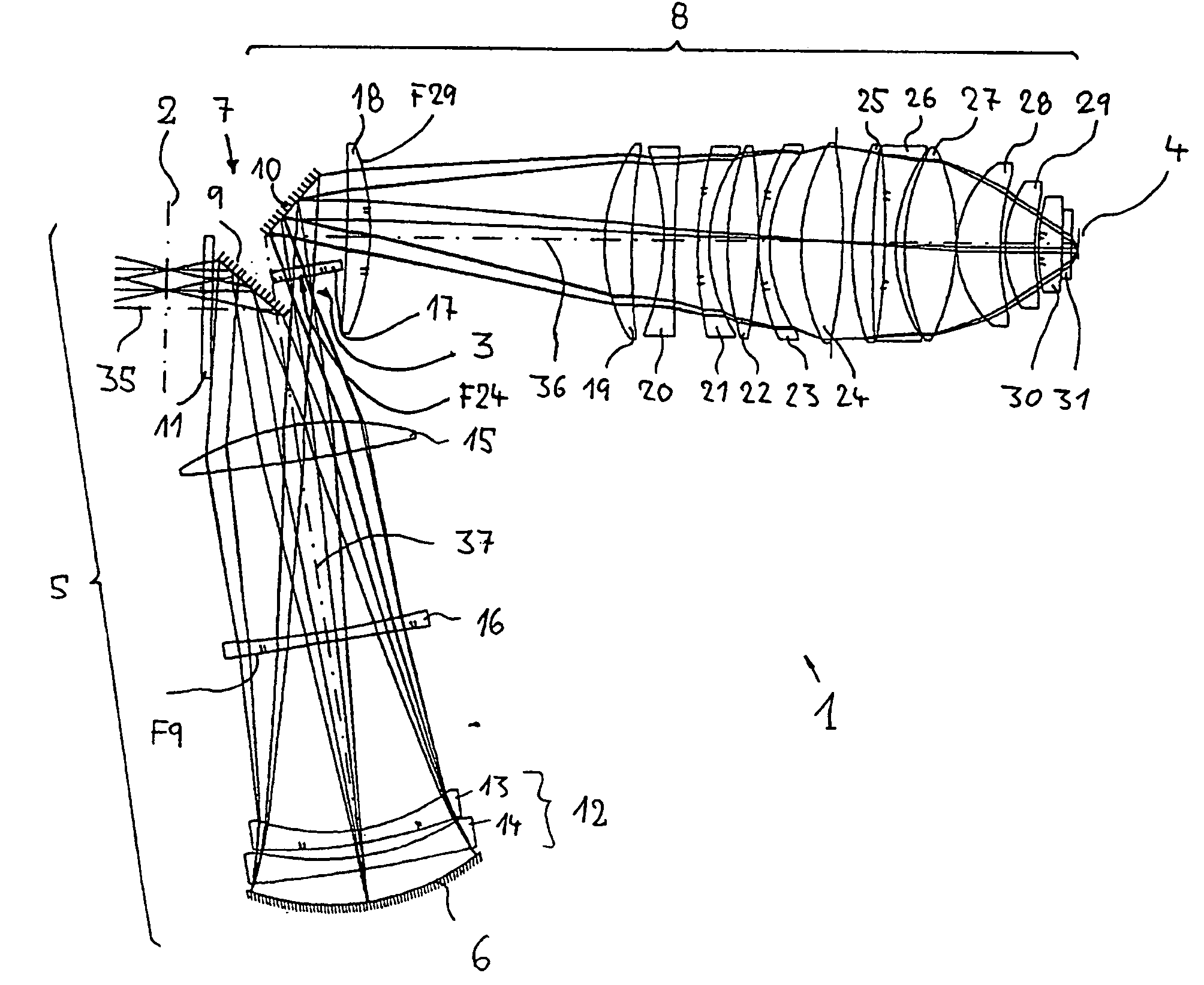
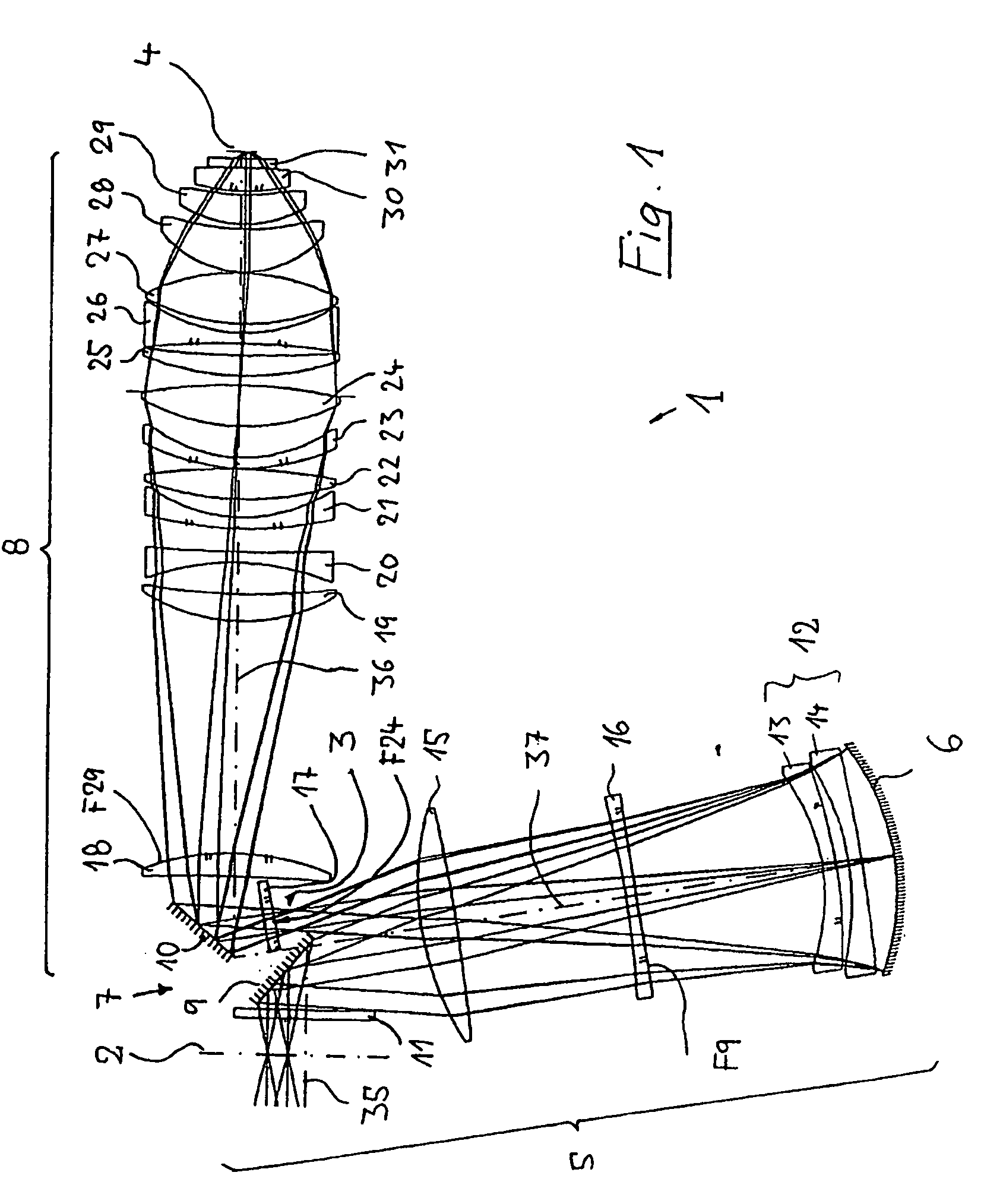
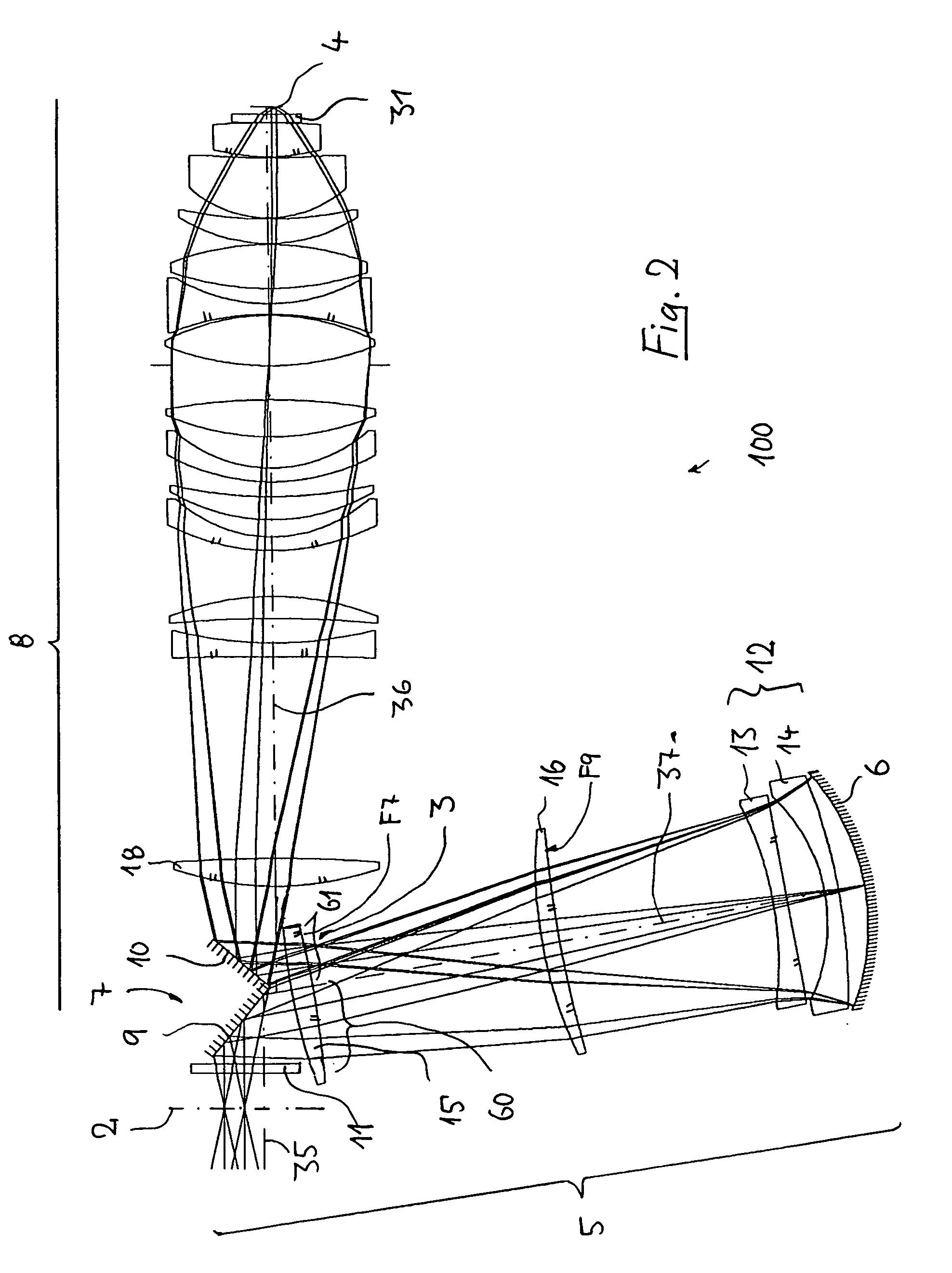
[0048]In the following description of preferred embodiments of the invention, the term “optical axis” shall refer to a straight line or sequence of straight-line segments passing through the centers of curvature of the optical elements involved. The optical axis is folded by deflecting mirrors or other reflective surfaces. Directions and distances shall be designated as “image-end” directions or distances if they are directed toward the image plane or a substrate to be exposed situated therein, and as “object-end” directions or distances if they are directed along that segment of the optical axis extending toward the object. In the case of those examples presented here, the object involved is either a mask (reticle) bearing the pattern of an integrated circuit or some other pattern, for example, a grating pattern. In the examples presented here, the image of the object is projected onto a wafer serving as a substrate that is coated with a layer of photoresist, although other types o...


PUM


Abstract

A catadioptric projection lens for imaging a pattern arranged in an object plane while creating a real intermediate image, having a catadioptric first lens section having a concave mirror and a beam-deflection device, as well as a dioptric second lens section that follows the catadioptric lens section, between its object plane and image plane. The beam-deflection device deflects radiation coming from the object plane to the concave mirror. Positive refractive power is arranged following the first reflective surface, between the latter and the concave mirror, within an optical near-field of the object plane, within which the height of the principal ray of the outermost field point of radiation coming from the object exceeds the marginal-ray height. The intermediate image is arranged prior to light which forms the intermediate image being reflected by a second reflective surface that is provided for the purpose of allowing arranging the object plane and image plane such that they will be parallel to one another.

Description

[0001]This is a Continuation of International Application PCT / EP02 / 13887, with an international filing date of Dec. 7, 2002, which was published under PCT Article 21(2) in English, and the disclosure of which is incorporated into this application by reference; the International Application PCT / EP02 / 13887, in turn, claims priority to U.S. Provisional Application Ser. No. 60 / 340,275 filed on Dec. 18, 2001.FIELD OF AND BACKGROUND OF THE INVENTION[0002]The invention relates to a catadioptric projection lens for imaging a pattern arranged in an object plane onto an image plane.[0003]Projection lenses of that type are employed on projection exposure systems, in particular wafer scanners or wafer steppers, used for fabricating semiconductor devices and other types of microdevices and serve to project patterns on photomasks or reticles, hereinafter referred to generically as “masks” or “reticles,” onto an object having a photosensitive coating with ultrahigh resolution on a reduced scale.[0...

Claims


Application Information

Patent Timeline
Patent Type & Authority Patents(United States)
IPC IPC(8): G02B17/00
CPCG02B17/0892G02B17/08
Inventor SHAFER, DAVID R.EPPLE, ALEXANDER
Owner CARL ZEISS SMT GMBH
Learn More