
Recovery of products from oil shale

a technology of oil shale and products, applied in the direction of fluid removal, borehole/well accessories, insulation, etc., can solve the problems of inability to recover inability to achieve total product recovery in situ, and high cost of oil shale removal from the ground, so as to achieve predictable and constant hydrocarbonaceous product recovery path, avoid expensive and time-consuming rubilization procedures, and preserve ground and surrounding terrain structural integrity

Inactive Publication Date: 2006-05-23
GENERAL SYNFUELS INT
View PDF7 Cites 193 Cited by
  • Summary
  • Abstract
  • Description
  • Claims
  • Application Information

AI Technical Summary

Benefits of technology

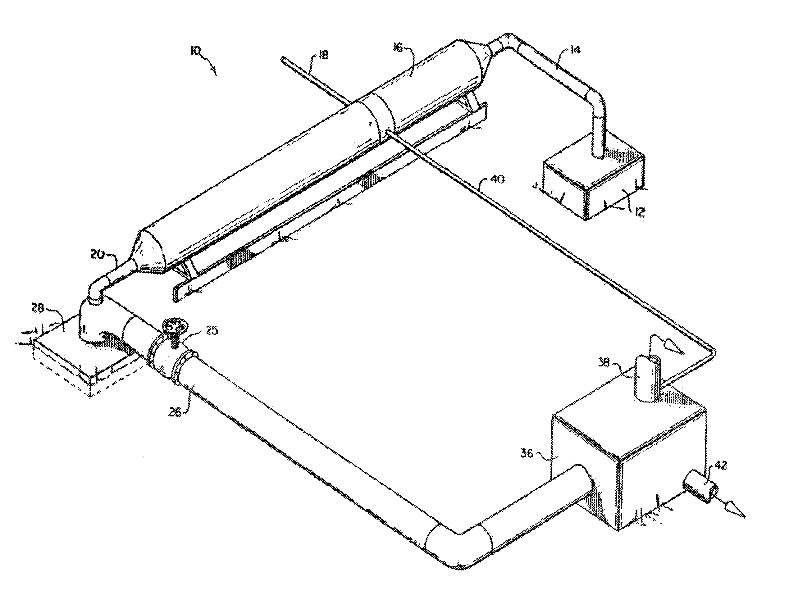
[0021]The effluent gas is transferred through the effluent gas conduit into a condenser where the effluent gas is allowed to expand and cool so as to condense a portion of the hydrocarbonaceous products into a liquid fraction. In the condenser, a remaining gaseous fraction of hydrocarbonaceous products is separated from the liquid fraction of hydrocarbonaceous products. The gaseous fraction is preferably scrubbed so as to separate an upgraded hydrocarbon gas from a waste inorganic gas containing carbon dioxide. A portion of the upgraded hydrocarbon gas may be recycled to the combustor to provide combustible material for fueling combustion within the combustor, while a portion of the waste inorganic gas may be recycled to the compressor for augmenting the supply of carbon dioxide in the processing gas. The carbon dioxide in the processing gas aids migration of the thermal energy front within the body of oil shale.
[0022]The present invention provides a process and system for recovering hydrocarbonaceous products from an in situ oil shale formation at potentially any depth to which a hole can be drilled in the oil shale formation. Thus, oil shale as deep as 3000 feet or deeper may be treated using the present invention. Moreover, the present invention provides an economical process and system for recovering hydrocarbonaceous products from all regions of an oil shale formation. Further, by eliminating the need for rubilization, expensive and time-consuming rubilization procedures are avoided, and the structural integrity of the ground and single hole for introducing the processing gas and for removing the hydrocarbonaceous products, and by not rubilizing the oil shale formation, the hole forms a single natural escape path for the hydrocarbonaceous products, thereby maximizing recovery of the products. Additionally, since the thermal energy front used to pyrolyze the kerogen in the present invention is a nonburning thermal energy front created by the introduction of the heated processing gas through the processing gas inlet conduit and into the hole, the problems of the prior art burning combustion fronts (produced, for example, by underground burners) are eliminated. Positioning of the compressor and combustor above the ground, outside the oil shale formation in accordance with the present invention, also allows for ‘more careful control of the pressure and temperature of the processing gas and thus of the processing conditions within the oil shale formation.
[0025]The present provides an economical process and system for recovering hydrocarbonaceous products from all regions of in situ oil shale formations. Expensive and time-consuming rubilization procedures are eliminated, and the structural integrity of the ground and surrounding terrain are preserved. Further, the recovery path of the hydrocarbonaceous products is predictable and constant, thereby maximizing recovery of the hydrocarbonaceous products.
[0026]In an embodiment, the oil shale is treated by a processing gas which is pressurized and heated outside of the oil shale formation so as to avoid the problems of burning combustion fronts and underground burners.

Problems solved by technology

When the oil shale is heated to about 250–400° F., destructive distillation of the kerogen occurs to produce products in the form of oil, gas, and residual carbon.
Clearly, in situ processes are economically desirable since removal of the oil shale from the ground is often expensive.
However, in situ processes are generally not as efficient as above-ground processes in terms of total product recovery.
Historically, prior art in situ processes have generally only been concerned with recovering products from oil shale which comes to the surface of the ground; thus, prior art processes have typically not been capable of recovering products from oil shale located at great depths below the ground surface.
For example, typical prior art in situ processes generally only treat oil shale which is 100 feet or less below the ground surface.
For economic reasons, it has been found generally uneconomical in the prior art to recover products from any other area of the oil shale bed than the mahogany zone.
Thus, there exists a relatively untapped resource of oil shale, especially deep-lying oil shale and oil shale outside of the mahogany zone, which have not been treated by prior art processes mainly due to the absence of an economically viable method for recovering products from such oil shale.
Another important disadvantage of many, if not most prior art in situ oil shale processes is that expensive rubilization procedures are necessary before treating the oil shale.
However, rubilization procedures are expensive, time-consuming, and often cause the ground surface to recede so as to significantly destroy the structural integrity of the underground formation and the terrain supported thereby.
This destruction of the structural integrity of the ground and surrounding terrain is a source of great environmental concern.
Rubilization of the oil shale in prior art in situ processes has a further disadvantage.
By rubilizing the oil shale formation, many different paths of escape are created for the products; the result is that it is difficult to predict the path which the products will follow.
Since the products have numerous possible escape paths to follow within the rubilized oil shale formation, the task of recovering the products is greatly complicated.
Other significant problems encountered in many prior art in situ processes for recovering products from oil shale stem from problems in controlling the combustion front established within the oil shale bed which pyrolyzes the kerogen.
Disadvantageously, each hole requires its own burner, which significantly increases the costs of the process.
Moreover, if the hole is not straight, problems are encountered in inserting the burner down the hole.
Further, it is extremely difficult, if not impossible, to use such burners to heat oil shale which is deeper than a few hundred feet below the ground surface.
Perhaps most importantly, the burning combustion fronts established by the burners in these processes are generally difficult to control since the burners are underground, thereby making it difficult to accurately measure the operation conditions and thus to optimize those conditions by controlling the burners.
For example, it is difficult to control or measure the amount of oxygen which must be supplied to the underground burners in order to support the burning combustion fronts; the result is poor stoichiometric control.
It is also difficult to control or accurately measure the temperature of the burning combustion front.
Since radiation heat from such underground burners typically results in uneven heating of the oil shale formation, hot and cold spots within the oil shale are often experienced.
The result of such underground burner systems is a poorly controlled and economically inefficient system for pyrolyzing the kerogen and recovering a substantial portion of the products from the oil shale.

Method used


Image

  • Recovery of products from oil shale
  • Recovery of products from oil shale
  • Recovery of products from oil shale

Examples


Embodiment Construction

[0031]While this invention is susceptible of embodiment in many different forms, there is shown in the drawings, and will herein be described in detail, exemplary embodiments, with the understanding that the present disclosure is to be considered as illustrative of the principles of the invention and not intended to limit the invention to the exemplary embodiments shown and described.

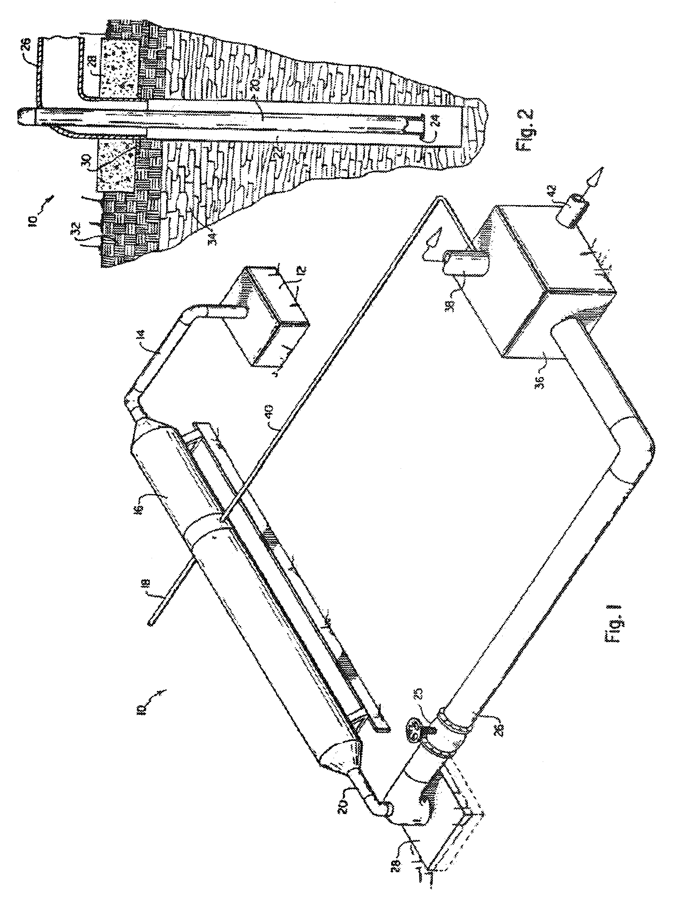
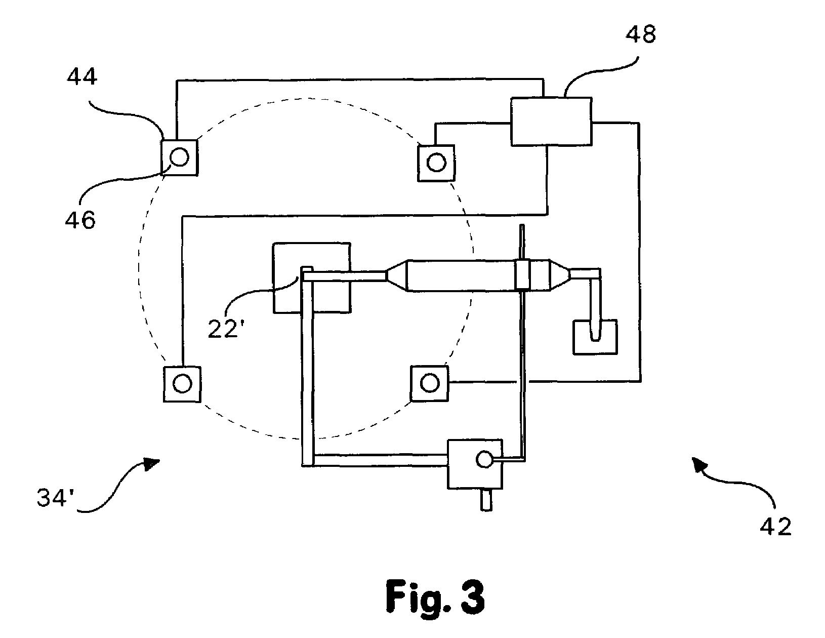
[0032]An embodiment of the process and system of the present invention, generally designated 10, is illustrated in FIG. 1. The system 10 includes a compressor 12 located above-ground, outside of the oil shale formation. The compressor 12 serves to pressurize a processing gas such that the processing gas within system 10 is maintained at a pressure in the range of about 5 psi to about 250 psi. It is contemplated that pressurizing the processing gas in a range of about 60 psi to about 110 psi, particularly at around 80 psi to 90 psi, will produce favorable results.

[0033]The system 10 further includes an a...


PUM


Abstract

A process and system for recovering hydrocarbonaceous products from in situ oil shale formations. A hole is drilled in the oil shale formation and a processing gas inlet conduit is positioned within the hole. A processing gas is pressurized, heated, and introduced through the processing gas inlet conduit and into the hole. The processing gas creates a nonburning thermal energy front within the oil shale formation so as to convert kerogen in the oil shale to hydrocarbonaceous products. The products are withdrawn with the processing gas through an effluent gas conduit positioned around the opening of the hole, and are then transferred to a condenser wherein a liquid fraction of the products is formed and separated from a gaseous fraction.

Description

FIELD OF THE INVENTION[0001]The present invention relates to the recovery of products from oil shale, and in particular, to a process and system for recovering hydrocarbonaceous products from oil shale.BACKGROUND OF THE INVENTION[0002]The term “oil shale” refers to a marlstone deposit interspersed with an organic mixture of complex chemical compounds collectively referred to as “kerogen.” The inorganic marlstone consists of laminated sedimentary rock containing mainly clay with fine sand, calcite, dolomite, and iron compounds. When the oil shale is heated to about 250–400° F., destructive distillation of the kerogen occurs to produce products in the form of oil, gas, and residual carbon. The hydrocarbonaceous products resulting from the destructive distillation of the kerogen have uses which are similar to petroleum products. Indeed, oil shale is considered to be one of the primary sources for producing liquid fuels and natural gas to supplement and augment those fuels currently pro...

Claims


Application Information

Patent Timeline
IPC IPC(8): E21B43/24E21B43/34
CPCE21B43/34E21B43/24
Inventor MCQUEEN, RONALD E.
Owner GENERAL SYNFUELS INT
Learn More