Layered aligned polymer structures and methods of making same

a polymer structure and alignment technology, applied in the field of layer alignment polymer structure and alignment method, can solve the problems of weak random orientation of collagen materials, deformation, and rapid deformation, and lack of desired mechanical and optical properties

Inactive Publication Date: 2006-05-23
PTS SPA +1
View PDF22 Cites 53 Cited by
  • Summary
  • Abstract
  • Description
  • Claims
  • Application Information

AI Technical Summary

Benefits of technology

[0007]It should be noted that deposition off the polymer solution can occur on a substrate having curved or spherical surfaces to result in stress-free interlayer boundaries. This embodiment is enabling for corneal constructs.

Problems solved by technology

Randomly oriented collagen materials are weak, and degrade quickly when exposed to mechanical stress.
Cast films of collagen can form a randomly oriented gel structure, which lacks desired mechanical and optical properties.

Method used


Image

  • Layered aligned polymer structures and methods of making same
  • Layered aligned polymer structures and methods of making same
  • Layered aligned polymer structures and methods of making same

Examples


example 1

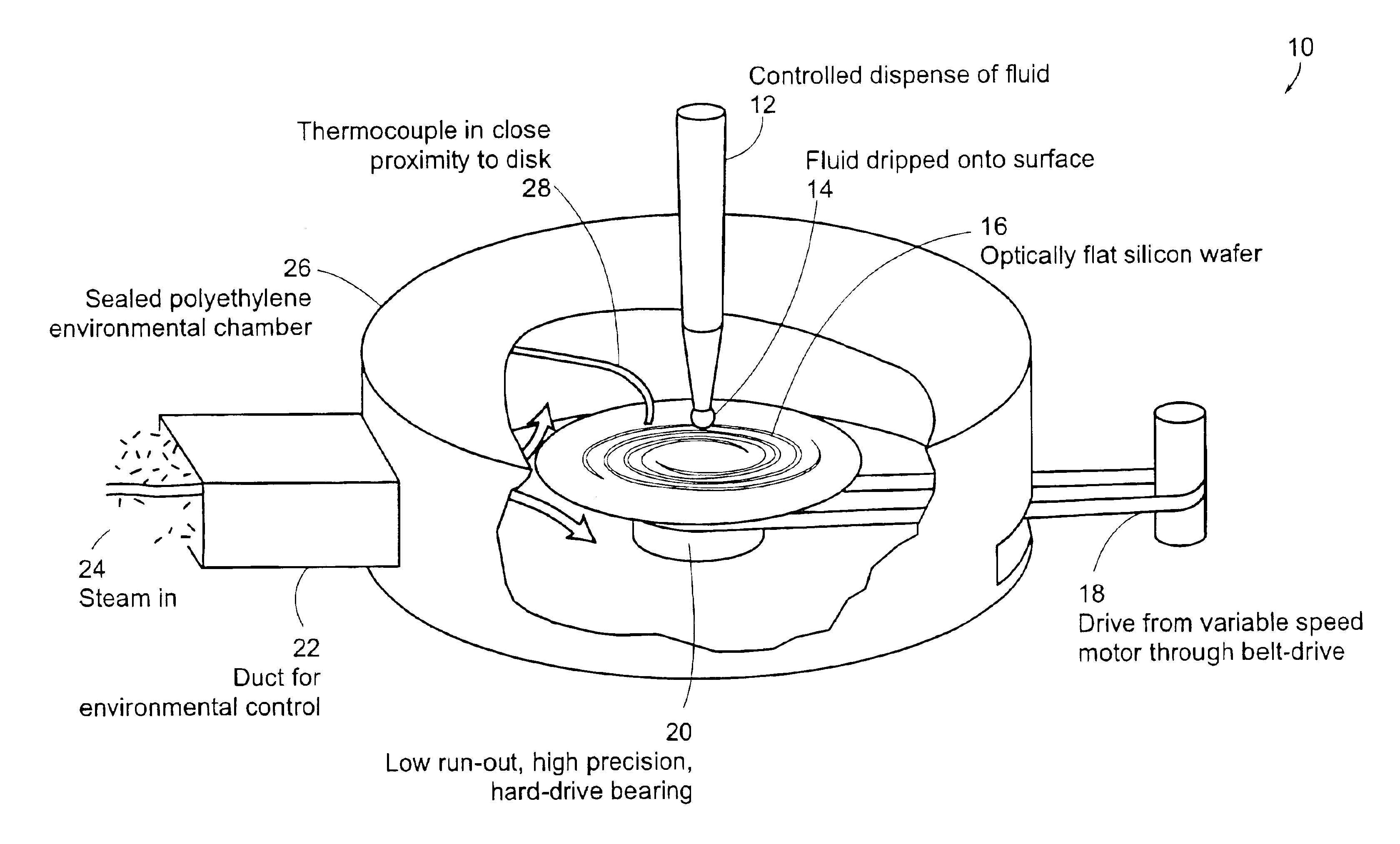
[0040]As one example of a preferred embodiment of this present invention, a metal disk is used as a deposition substrate. The disk is mounted on a spin-coating-type apparatus. A chamber is built around the apparatus to control the temperature and the relative humidity. The disk can be spun at a specified rate. This embodiment is illustrated in FIG. 1.

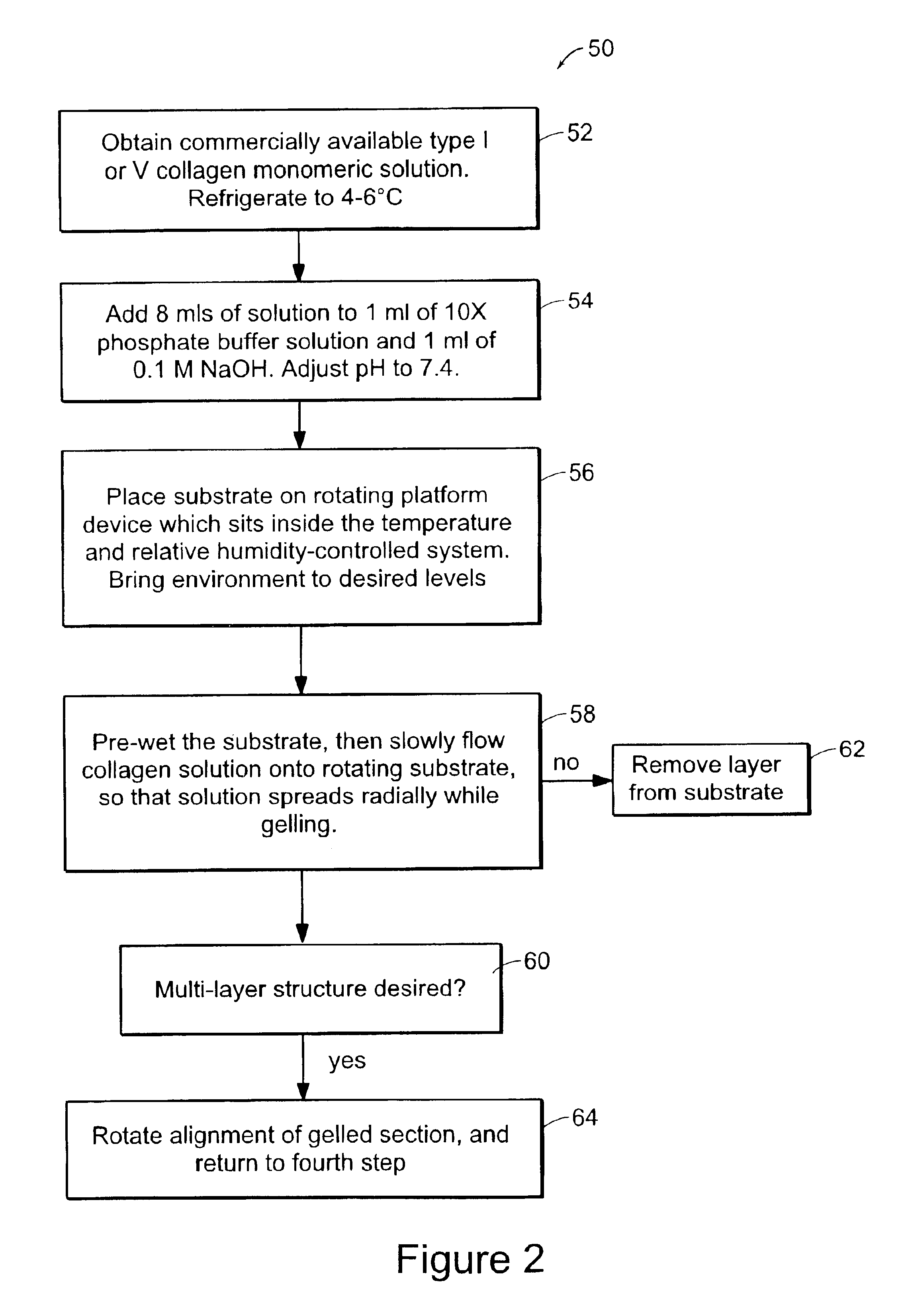
[0041]A solution of Vitrogen collagen is chilled to 4-6° C. Eight ml of the collagen solution is mixed with 1 ml of 10× phosphate-buffered saline solution (0.2 M Na2HPO4, 1.3M NaCl, pH=7.4) and 1 ml of 0.1M NaOH. The pH is adjusted to 7.4±0.2 by adding 0.1M HCl. The solution is warmed to the test temperature, then steadily dripped onto the rotating substrate 16. The collagen gels form a uniform sub-micron thick sheet. This process is described with respect to the flow chart illustrated in FIG. 2. Nematic stacks are prepared by cutting out sections of the radially-aligned collagen fiber sheets, and stacking them orthogonally by hand. Ele...

example 2

[0042]As a second example of a preferred embodiment of the present invention, sample disks 104 with T-slots cut into their surfaces are mounted on a disk 102 rotating at a specified rate as shown in FIGS. 4A and 4B. In accordance with a preferred embodiment of the present invention, the first layer of aligned associating fibrils is prepared by flowing the polymeric solution into channel of sample disks, which are on the rotating bottom disk. The centrifugal motion generates a shearing flow, which produces a thin layer and aids in aligning the growing associating polymers. The sample disks are then rotated 90 degrees, or to another specified angle, and the second layer is applied, which aligns with the specified angle relative to the first. A solution of Vitrogen collagen is chilled to 4-6° C. Eight ml of the collagen solution is mixed with 1 ml of 10×phosphate-buffered saline solution (0.2 M Na2HPO4, 1.3M NaCl, pH=7.4) and 1 ml of 0.1M NaOH. The pH is adjusted to 7.4±0.2 by adding 0...

example 3

[0043]Another preferred embodiment of the present invention includes the monomer solution being placed in a temperature-controlled bowl as shown in FIGS. 5A-5C. In FIG. 5A, the polymer solution is subjected to a shearing flow by rotating the ball in one direction, or by oscillating in the same rotation plane. The polymer associates during this process. In FIG. 5B, the ball is rotated or oscillated in the orthogonal plane, to generate a layer of associated polymers orthogonal to the first layer. In FIG. 5C a three-dimensional (3D) rendering of the method is illustrated. A ball 122 with a diameter a few microns smaller than the bowl 128 diameter is placed in the bowl. A shaft 126 attached to the ball rotates the ball first in one direction, generating a shearing flow, during which time the monomer polymerizes. After a designated gelation period, fresh monomer solution may be introduced to the bowl, and the ball is rotated in the orthogonal direction, creating a layer orthogonally-alig...


PUM

PropertyMeasurementUnit
thicknessaaaaaaaaaa
angleaaaaaaaaaa
flow rateaaaaaaaaaa

Abstract

This invention includes a method of producing a thin, oriented layer of polymer material. The material is preferably produced by the method of introducing a shearing flow to a free surface in a predominantly monomeric solution of the self-assembling polymer sub-units, and inducing polymerization or growth of the monomer while in this shearing flow. The system for forming the oriented layer of material provides relative movement between a delivery system and the substrate on or over which the material is deposited. The rate of flow of the material from the delivery system and the relative velocity between the deposition surface and the material as it is delivered to the surface are controlled to properly orient the material at the desired thickness. These rates can be adjusted to vary the properties of the film in a controlled manner. Preferred embodiments include either angular or linear relative movement between the delivery system and the substrate.

Description

CROSS REFERENCES TO RELATED APPLICATIONS[0001]This application claims the benefit of U.S. Provisional Application No. 60 / 337,286 filed on Nov. 30, 2001, the entire contents of which are incorporated herein by reference in its entirety.BACKGROUND OF THE INVENTION[0002]Accurate control of the orientation of polymeric structure in thin layers is desired to maximize their mechanical, chemical, and optical properties. While orientation can be performed through mechanical means, it is often more desirable to orient the structure during the polymerization process, particularly if the process involves polymerizing the system into a specific final shape, where further mechanical manipulation is unfeasible.[0003]Biomedical components often require oriented structures. Tendons, for example, contain highly oriented collagen fibrils, and the spinal intervertebral disc is composed mainly of oriented crystalline collagen fibrils and amorphous hydrophilic proteoglycan. The prevalence of oriented co...

Claims


Application Information

Patent Timeline
Patent Type & Authority Patents(United States)
IPC IPC(8): B05D3/12A61L27/24A61L27/38A61L27/50B29C41/04B29C41/22B29C41/36B29C41/52B29C48/08B29C67/00B29C67/24C08L89/06D01D5/38D01F4/00
CPCA61L27/24D01D5/18A61L27/50B29C41/045B29C41/22B29C41/36B29C41/52B29C47/0004B29C47/0021B29C67/0003B29C67/24C08L89/06D01D5/38D01F4/00A61L27/38A61L2400/18B29C2037/90B29K2089/00B29K2995/005B29C48/022B29C48/08
Inventor BRAITHWAITE, GAVIN J. C.RUBERTI, JEFFREY W.
Owner PTS SPA
Why Eureka
Try Eureka