
Use of analog-valued floating-gate transistors to match the electrical characteristics of interleaved and pipelined circuits

a floating-gate transistor and electrical characteristic technology, applied in the field of analog-valued floating-gate transistors, can solve the problems of device-to-device mismatch, inability to match the electrical characteristics of pipelined circuits, and inability to achieve the same circuit elements

Active Publication Date: 2006-05-23
SYNOPSYS INC
View PDF71 Cites 36 Cited by
  • Summary
  • Abstract
  • Description
  • Claims
  • Application Information

AI Technical Summary

Problems solved by technology

In practice, however, no two circuit elements are the same.
For example, in integrated circuit implementations of such systems, device-to-device mismatches are the result of process and temperature gradients.
Such mismatches are problematic as they can result in subsystem pathways not having identical gain, offset, signal delay, clock timing, frequency response, and / or transfer function.
Consequently, regardless of how well the individual processing elements perform on their own, errors can result in time-interleaved and pipelelined systems due to device-to-device mismatches.
Some of these approaches, which may or may not be useful in reducing device mismatch in time-interleaved and pipelined systems, include using large transistors, using lasers to trim resistors or fuses, and using capacitors to dynamically match devices in response to on-chip error signals.
Unfortunately, each of these approaches has significant disadvantages.
For instance, large transistors require large currents to operate at high speeds, consume large silicon area and power, and do not compensate for temperature or aging errors.
Similarly, laser-trimming resistors or fuses necessitates use of large resistors or fuses, requires time-consuming laboratory trimming, and again does not compensate for temperature or aging errors.
Finally, using capacitors to dynamically trim circuit elements requires wideband error-feedback loops and frequent updates, because on-chip capacitors leak due to the thermal generation of carriers in pn junctions.

Method used


Image

  • Use of analog-valued floating-gate transistors to match the electrical characteristics of interleaved and pipelined circuits
  • Use of analog-valued floating-gate transistors to match the electrical characteristics of interleaved and pipelined circuits
  • Use of analog-valued floating-gate transistors to match the electrical characteristics of interleaved and pipelined circuits

Examples


Embodiment Construction

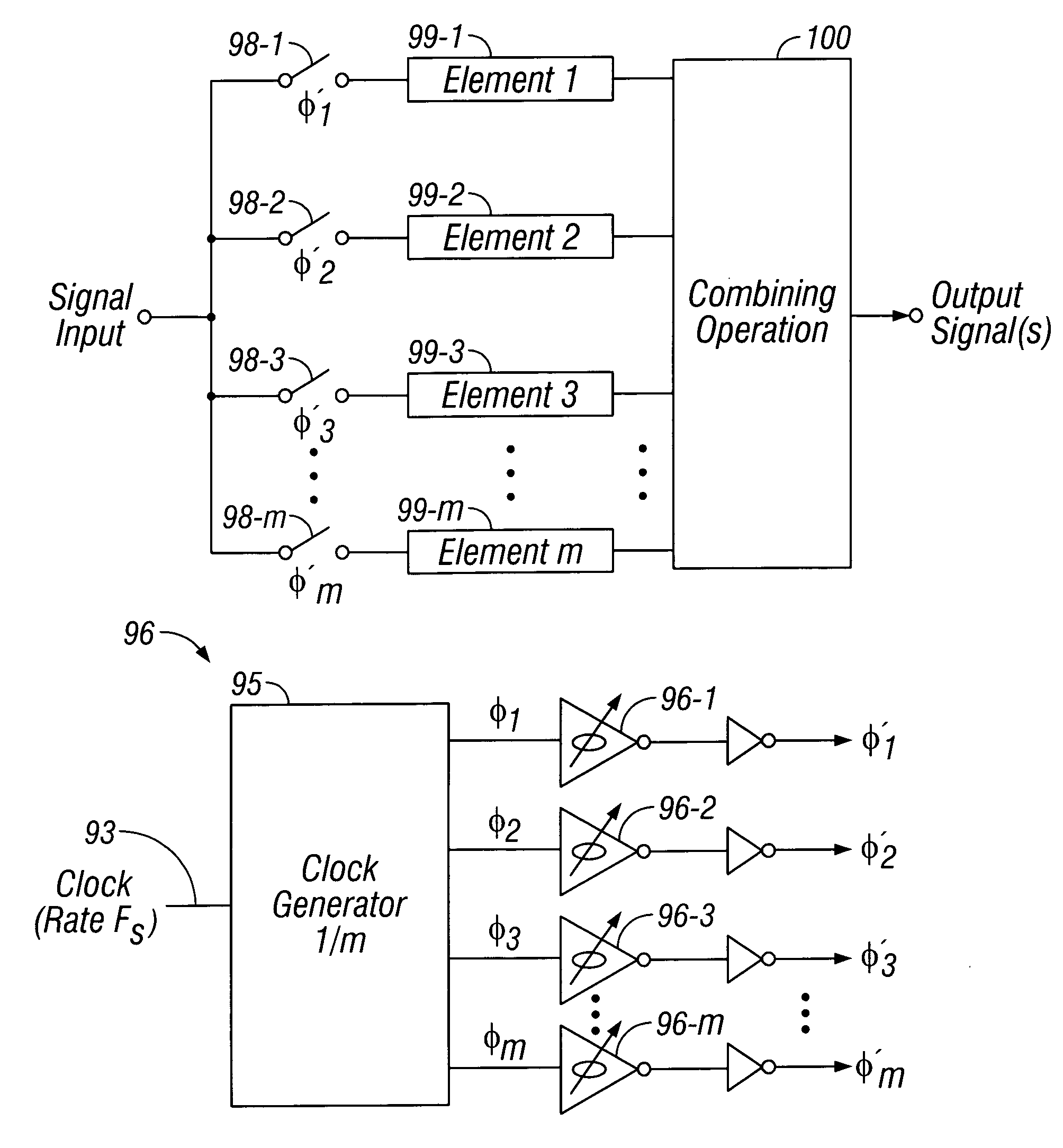
[0058]Embodiments of the present invention are described herein in the context of using analog-valued floating-gate transistors as trim devices in time-interleaved and pipelined circuits. Those of ordinary skill in the art will realize that the following detailed description of the present invention is illustrative only and is not intended to be in any way limiting. Other embodiments of the present invention will readily suggest themselves to such skilled persons having the benefit of this disclosure. Reference will now be made in detail to implementations of the present invention as illustrated in the accompanying drawings. Unless indicated otherwise, the same reference indicators will be used throughout the drawings and the following detailed description to refer to the same or like parts.

[0059]In the interest of clarity, not all of the routine features of the implementations described herein are shown and described. It will of course be appreciated that, in the development of any...


PUM


Abstract

Methods of and apparatuses for matching the signal delay, clock timing, frequency response, gain, offset, and / or transfer function of signal pathways in electrical circuits such as, for example, time-interleaved and pipelined circuits using analog-valued floating-gate MOSFETs are disclosed. The methods and apparatuses disclosed are applicable to a variety of circuits, including but not limited to, sample-and-hold or track-and-hold circuits, quadrature mixers, analog-to-digital converters (ADCs), digital-to-analog converters (DACs), analog or digital filters, and amplifiers.

Description

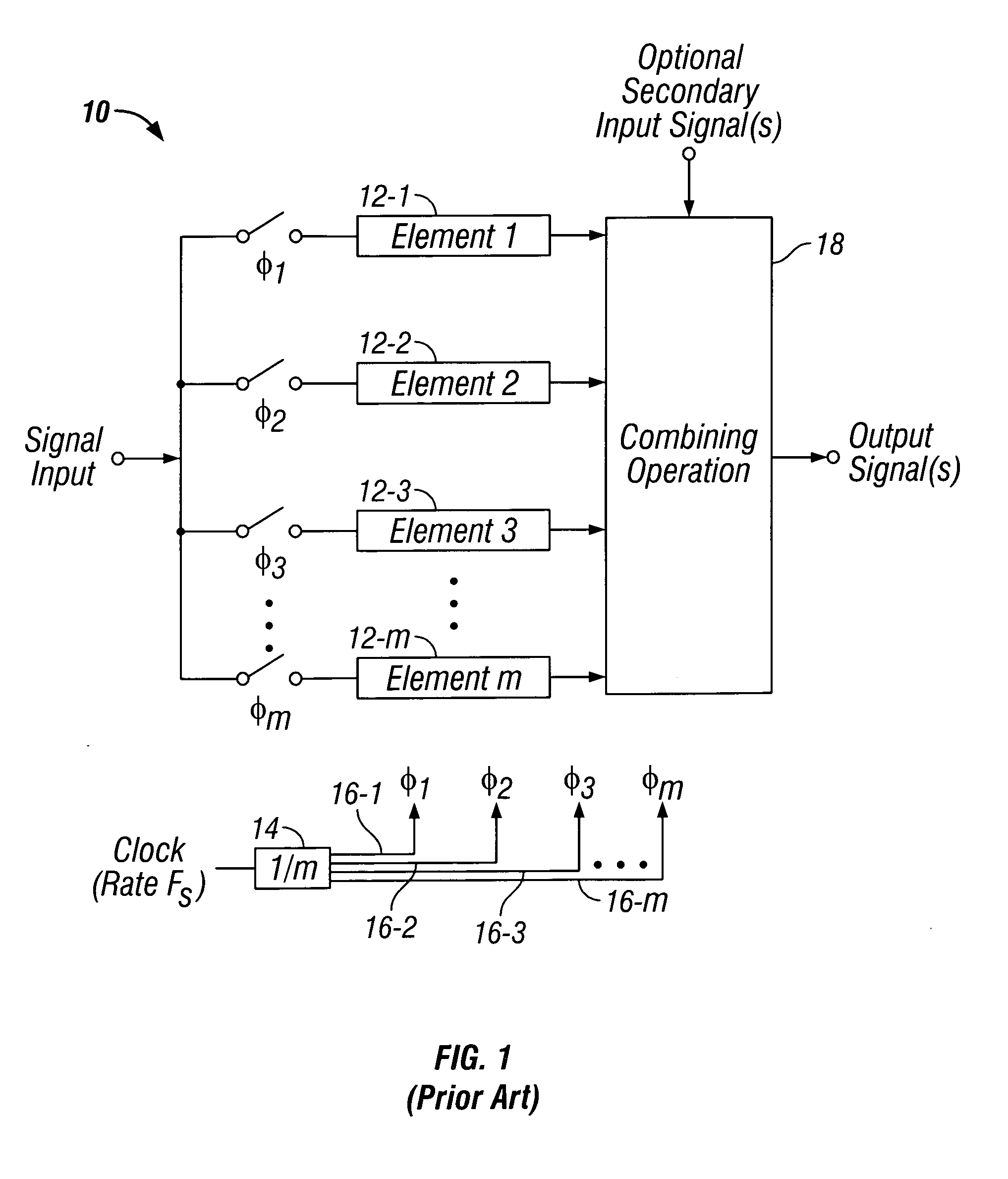
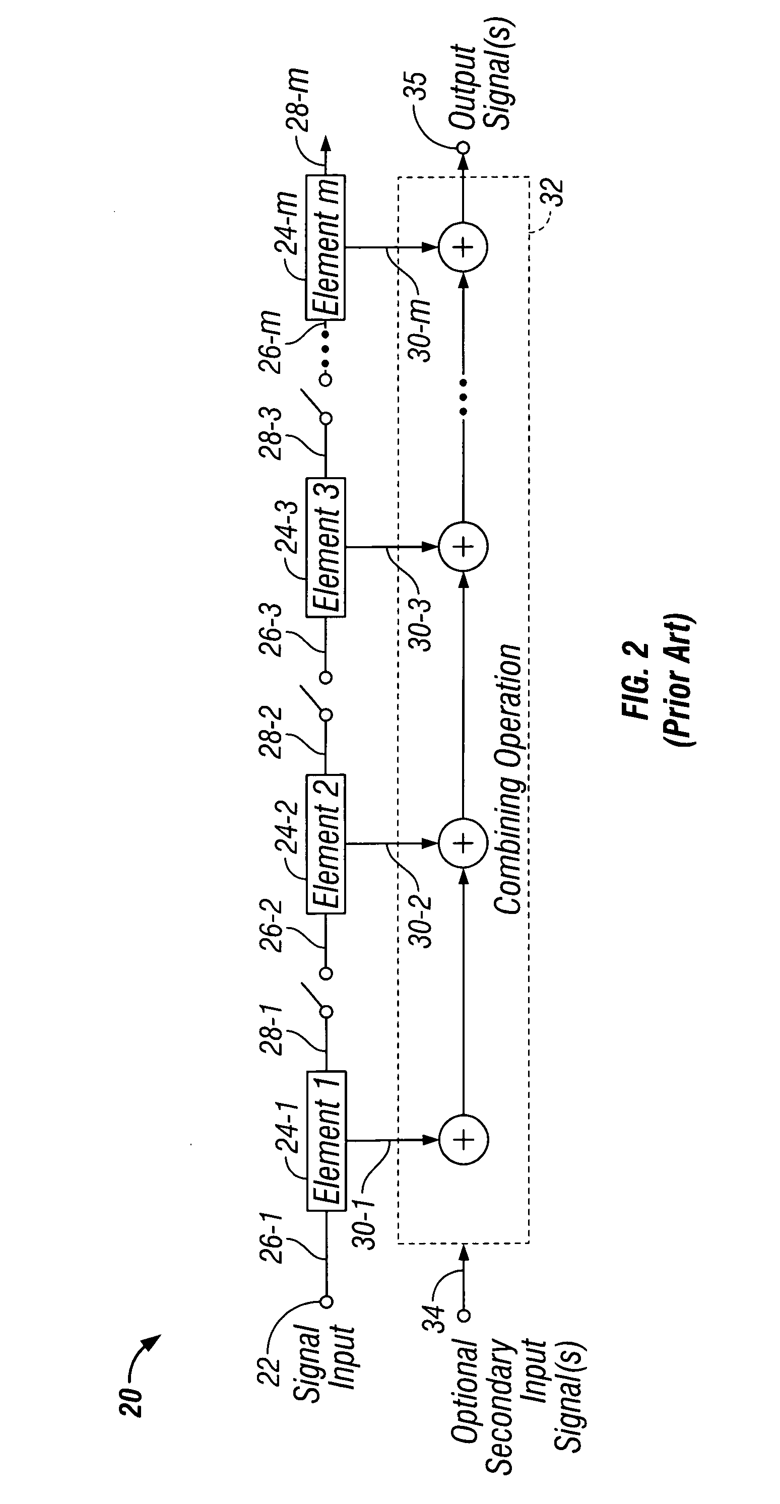
CROSS-REFERENCE TO RELATED APPLICATIONS[0001]This application claims the benefit of U.S. Provisional Application No. 60 / 417,072, filed on Oct. 8, 2002.FIELD OF THE INVENTION[0002]The present invention is directed to the use of analog-valued floating-gate transistors as trim devices in electrical circuits such as, for example, time-interleaved and pipelined circuits.BACKGROUND OF THE INVENTION[0003]To improve the performance of radio-frequency, analog, or mixed-signal circuits, engineers often use techniques know as interleaving and pipelining. Interleaving is a technique that allows a signal to be processed in multiple parallel pathways at successive instants in time. Pipelining is a technique that allows a signal to be processed multiple times serially at successive instants in time. Both techniques allow multiple circuit elements to operate on a single analog signal, thereby improving the processing performance of the circuit. Performance in this context might mean, for example in...

Claims


Application Information

Patent Timeline
IPC IPC(8): H03H11/26G06F1/10G11C27/00G11C27/02H03K5/00H03K5/135H03K5/15H03K5/24H03M1/06H03M1/12H03M1/16H03M1/44
CPCG06F1/10G11C27/005G11C27/024H03K5/135H03K5/1502H03K5/2481H03M1/0602H03K5/249H03M1/442H03K2005/00026H03K2005/00058H03K2005/00084H03M1/1215H03M1/164
Inventor DIORIO, CHRISTOPHER J.HUMES, TODD E.THOMAS, MICHAEL
Owner SYNOPSYS INC
Learn More