Long-life vacuum system for energy storage flywheels

a vacuum system and energy storage technology, applied in the direction of positive displacement liquid engines, electric generator control, machines/engines, etc., can solve the problems of ineffective hydrogen capture of physical type getters, difficult removal of gases by this method, and large quantity and rate of gas evolution, etc., to achieve easy sorbed, high rate, and easy sorbed

Inactive Publication Date: 2006-05-30
INDIGO ENERGY INC
View PDF54 Cites 31 Cited by
  • Summary
  • Abstract
  • Description
  • Claims
  • Application Information

AI Technical Summary

Benefits of technology

[0012]The invention is a vacuum system and method of maintaining vacuum in a flywheel power source that maintains the low pressure inside a flywheel chamber for the life of the power source. The vacuum system works by combining the use of a steel flywheel housed inside a metal vacuum chamber of the power source, with the use of a chemical type metal alloy non-evaporable getter that cooperatively matches the outgassing of the flywheel and chamber by sorbing those gases that are released. In contra, use of higher speed and lighter weight composite material flywheels for storing energy in the power source would result in up to 1000 times or greater outgassing load, which would make removal of the gases by this method extremely difficult. Not only would the quantity and rate of gas evolution be extremely large for a system employing a composite material flywheel, the gases include much water vapor as well as larger molecules which are much more difficult to getter by chemical type getters. The use of a steel flywheel has been found to outgas primarily hydrogen and this is gas most readily sorbed by the chemical type metal alloy non-evaporable chemical type getters. In contrast, physical type getters are can not effectively trap hydrogen Although, steel flywheels contain nearly 70 times more internal nitrogen gas, the hydrogen is many times more soluble in the steel and thus outgases at a higher rate. Therefore, sorbing the large quantity of hydrogen is required to maintain the vacuum. Because both the getter material and the flywheel are constructed of metals, it becomes understandable that both would have similar differing solubilities for different gasses. The hydrogen that is readily released from the flywheel in vacuum due to its higher internal concentration, becomes readily sorbed by the alloy getter material. Other gases such as carbon monoxide, carbon dioxide, nitrogen and oxygen are also outgassed and sorbed, but at slower rates. The non-evaporable getter has the ability to take in these gases at a lower temperature than the steel of the flywheel because of the elements in its construction and because of use of alloying which lowers the activation and operation temperature. One common commercially available metal alloy non-evaporable getter material that is preferable for use with the invention is zirconium-vanadium-iron
[0014]In one embodiment of the invention, the getter in the flywheel power source is reactivated throughout the life of the flywheel system by reheating it through use of an integral heater. The heater is preferably triggered by a timer instead of a vacuum gauge to increase the system reliability. The power for the heater can be taken directly from the energy stored in the flywheel. When the getter is being reactivated, some stored hydrogen becomes released and is later sorbed. Because the flywheel is constructed of steel, it has a high thermal conductivity, capacity and capability along with a lower operating tip speed because of its mass. This makes the release of hydrogen during reactivation not problematic when the flywheel is spinning. The vacuum can be regenerated without shutting the system down Although it is common to heat non-evaporable getters continuously in operation at a lower temperature than the activation temperature to increase the sorption rate of gases, this could potentially use up the getter in a flywheel system much too quickly by yielding a lower pressure than required for a shorter time.
[0015]In a further embodiment of the invention, the outgassing of the steel flywheel can be reduced by performing the steel tempering operation in a vacuum prior to installation in the containment vessel. This reduces the quantity of non-evaporable getter required to maintain the vacuum The steel in the flywheel must be heat treated, quenched and tempered to achieve the high strength and toughness required for high speed operation. The tempering process involves heating the steel to a tempering temperature, in many cases between 800° F. and 1200° F. and holding it at that temperature for several hours. The brittle martensite internal structure produced during heat treatment becomes transformed to tempered martensite. Because the solubility of gases in metals is related to the temperature, the steel flywheel material can have much of its gas removed while being held at this high temperature. Vacuum furnaces are many times used to improve the mechanical properties and appearances of metals. In this case, the use of vacuum in the tempering process reduces the outgassing load of the steel flywheel in operation in vacuum. Upon removal from the tempering, water and other molecules become attached to the material surface and the flywheel outgassing would still benefit from some lower temperature heating during installation of the flywheel system vacuum. However, the longer term outgas rate can be reduced by the process.
[0016]In yet a further embodiment of the invention, the electronics of the flywheel power source are used to signal an alarm and or prevent achieving or maintaining fill speed of the flywheel when the pressure in the vacuum chamber is found to be too high. This can be done either by simply current limiting to the motor power since the flywheel is constructed from steel and is less likely to overheat, or alternatively the electronics calculating the drag through use of the motor power, flywheel speed and flywheel acceleration. The calculation method allows the flywheel to detect any vacuum level problems and also any bearing or motor / generator problems prior to accelerating to full speed. The determination of excess drag for a given state of flywheel operation can also be used to trigger reactivation of the getter for improving the vacuum.

Problems solved by technology

In contra, use of higher speed and lighter weight composite material flywheels for storing energy in the power source would result in up to 1000 times or greater outgassing load, which would make removal of the gases by this method extremely difficult.
Not only would the quantity and rate of gas evolution be extremely large for a system employing a composite material flywheel, the gases include much water vapor as well as larger molecules which are much more difficult to getter by chemical type getters.
In contrast, physical type getters are can not effectively trap hydrogen Although, steel flywheels contain nearly 70 times more internal nitrogen gas, the hydrogen is many times more soluble in the steel and thus outgases at a higher rate.
The vacuum can be regenerated without shutting the system down Although it is common to heat non-evaporable getters continuously in operation at a lower temperature than the activation temperature to increase the sorption rate of gases, this could potentially use up the getter in a flywheel system much too quickly by yielding a lower pressure than required for a shorter time.

Method used


Image

  • Long-life vacuum system for energy storage flywheels
  • Long-life vacuum system for energy storage flywheels
  • Long-life vacuum system for energy storage flywheels

Examples


Embodiment Construction

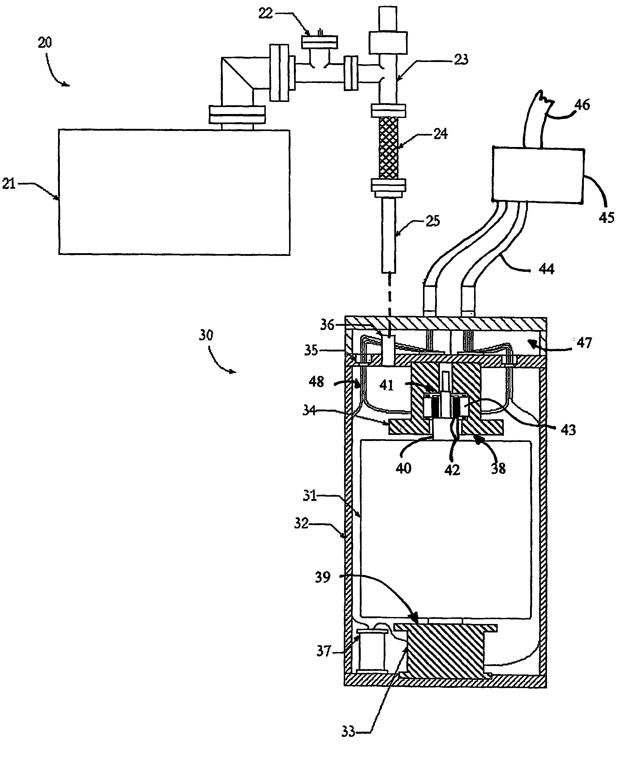
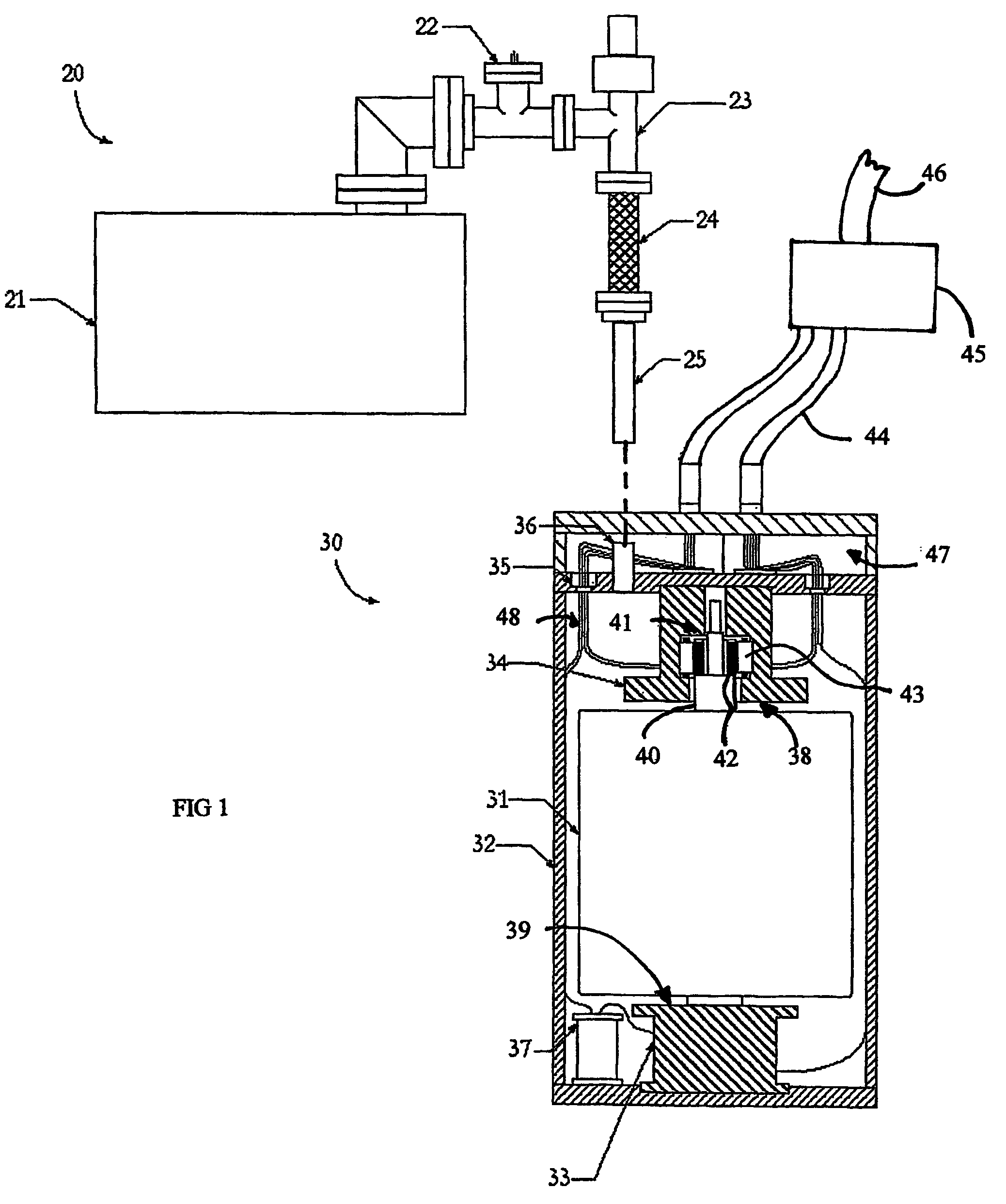
[0021]Tuning to the drawings, wherein like reference characters designate identical or corresponding parts, FIG. 1 shows a flywheel power source 30 that has been disconnected from an external initial vacuum-pumping system 20. In accordance with the invention, the flywheel power source 30 uses a steel flywheel 31 that is enclosed inside a metal chamber 32 for storing energy. The flywheel steel is preferably an alloy for high strength and deep hardenability with 4340 being preferred for having relatively good properties at low cost. The chamber is maintained internally at a low pressure for reduction of aerodynamic drag on the flywheel 31. The container 32 can be constructed of steel, stainless steel aluminum or of other metals, however carbon steel is preferred for low cost. Although some prior art flywheel systems have used ‘O’ rings or epoxy bonding to seal the vacuum, the vacuum chamber of the invention is preferably sealed using metal welding, brazing or soldering for lower outga...


PUM


Abstract

The invention, intended primarily for use in a steel flywheel power source (30), provides a vacuum system and a method of maintaining a vacuum inside a flywheel chamber (32) for the life of the power source (30). The vacuum system combines the use of cleaning and de-gassing treatments in the chamber (32) and vacuum tempering of the steel flywheel (31) with the use of a chemical type metal alloy nonevaporable getter, such as zirconium-vanadium-iron, that cooperatively matches the outgassing of the flywheel (31) and chamber (32) by sorbing those gases that are released. The getter may be reactivated throughout the life of the flywheel system by reheating it with an integral heater that is triggered by a timer instead of a vacuum gauge to increase the system reliability, using power taken directly from the energy stored in the flywheel. The electronics (45) of the flywheel power source are used to signal an alarm or prevent achieving or maintaining full speed of the flywheel when the vacuum in the chamber degrades.

Description

[0001]This is related to U.S. Provisional Applications No. 60 / 224,463 filed on Aug. 10, 2000, No. 60 / 237,310 filed on Oct. 2, 2000, and No. 60 / 257,936 filed on Dec. 20, 2000 and to International Application PCT / US01 / 25199 filed on Aug. 10, 2001 and entitled “Long-Life Vacuum System for Energy Storage Flywheels, which was published by the World International Patent Organization as International Publication No. WO 02 / 15366 on Feb. 21, 2002.[0002]This invention pertains to a vacuum system for energy storage flywheels and more particularly to a vacuum system and method of maintaining vacuum in a flywheel power source that employs a steel flywheel for storing energy. The vacuum system maintains the required low pressure inside a flywheel chamber to prevent excessive aerodynamic drag for the life of the power source and is reliable, maintenance-free and low cost.BACKGROUND OF THE INVENTION[0003]Flywheels have been used for many years as energy storage devices. They have often been used as...

Claims


Application Information

Patent Timeline
Patent Type & Authority Patents(United States)
IPC IPC(8): H02K7/02F16F15/30H02K16/00H02K47/04H02P9/42
CPCH02K7/025Y10T74/2117Y02E60/16
Inventor GABRYS, CHRISTOPHER W.CAMPBELL, DAVID R.
Owner INDIGO ENERGY INC
Why Eureka
Try Eureka