Supercharge Your Innovation With Domain-Expert AI Agents!

Capillary array and capillary array photodetector

a capillary array and photodetector technology, applied in the field of capillary array and capillary array photodetector, can solve the problems of complicated scattering light, and achieve the effects of improving detection limits, reducing crosstalk, and increasing dynamic rang

Inactive Publication Date: 2006-05-30
HITACHI LTD
View PDF20 Cites 3 Cited by
  • Summary
  • Abstract
  • Description
  • Claims
  • Application Information

AI Technical Summary

Benefits of technology

The present invention provides a multi-focus system with a capillary array that reduces crosstalk, which is the interference of signals from adjacent capillaries. Crosstalk occurs when emissions from a laser beam or capillaries reflect and scatter on the surface of the substrate, which causes signals to overlap and be detected by a photodetector. The invention solves this problem by providing a substrate with a perforation piercing from the capillary holding surface to the back side of the substrate in an area opposing to the portions of the capillaries that receive the laser beam irradiation. The invention also includes scattered light shielding means placed on the capillaries for shielding areas at which adjacent capillaries contact with each other.

Problems solved by technology

Further, the scattered light becomes more complicated due to the planar substrate on which the capillaries are aligned.
There is a problem of “crosstalk” in a multi-focus system that a part of emissions from a certain capillary overlaps with a location of emissions of an adjacent capillary due to the scattered light, i.e., signals of the certain capillary are detected as signals of the adjacent capillary.

Method used


Image

  • Capillary array and capillary array photodetector
  • Capillary array and capillary array photodetector
  • Capillary array and capillary array photodetector

Examples


first embodiment

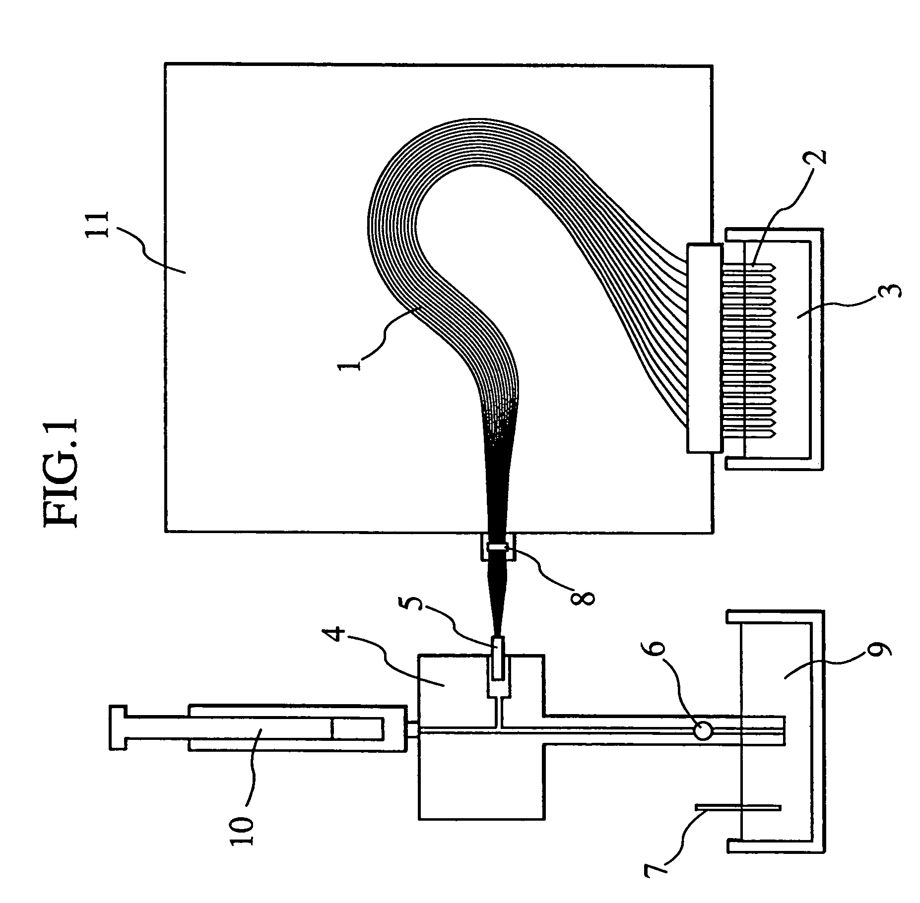
[0036]FIG. 1 is a schematic view of an electrophoresis device according to the present invention. At one end of a capillary array 1, an electrode (sample inlet end) 2 is formed so that it can apply a negative voltage. The voltage is applied after soaking the negative electrode 2 into a solution containing the sample DNA (not shown) in the case of injecting the sample DNA, and after soaking the negative electrode 2 into a buffer solution 3 in the case of conducting electrophoresis of the injected sample DNA. Formed on the other end of the capillary array 1 is a connecting portion 5 for connecting the capillary array 1 with a gel block 4 from which an electrophoresis medium gel is injected into a capillary. In order to fill the capillary with the electrophoresis medium gel, a valve 6 is closed and a syringe 10 is pressed so that the gel retained in the syringe 10 is injected into the capillary 1. In the case of conducting the electrophoresis, the valve 6 is opened, and a voltage is ap...

second embodiment

[0051]A second embodiment of the present invention will be described with reference to FIGS. 10 and 11. FIG. 10, which corresponds to FIG. 6, is a sectional view of another example of a capillary array photodetector and a vicinity of an area on which laser beam is irradiated. FIG. 11 is a front view of FIG. 10.

[0052]In the present embodiment, as shown in FIGS. 10 and 11, a capillary array holder 81 placed at the rear of the planar glass substrate 20 is formed with a perforation 80, in addition to th perforation 72 formed on the planar glass substrate when the capillary array is viewed from the fluorescence detector provided in the capillary array photodetector. Further, a cavity 84 is formed on a side facing to the capillary array of an array fixing means 82 for fixing the capillary array, so that emissions from the capillaries 71 enter the cavity 84. A black coating that is remarkably low in reflectance is applied on an inner wall 83 of the cavity 84 provided on the array fixing me...

third embodiment

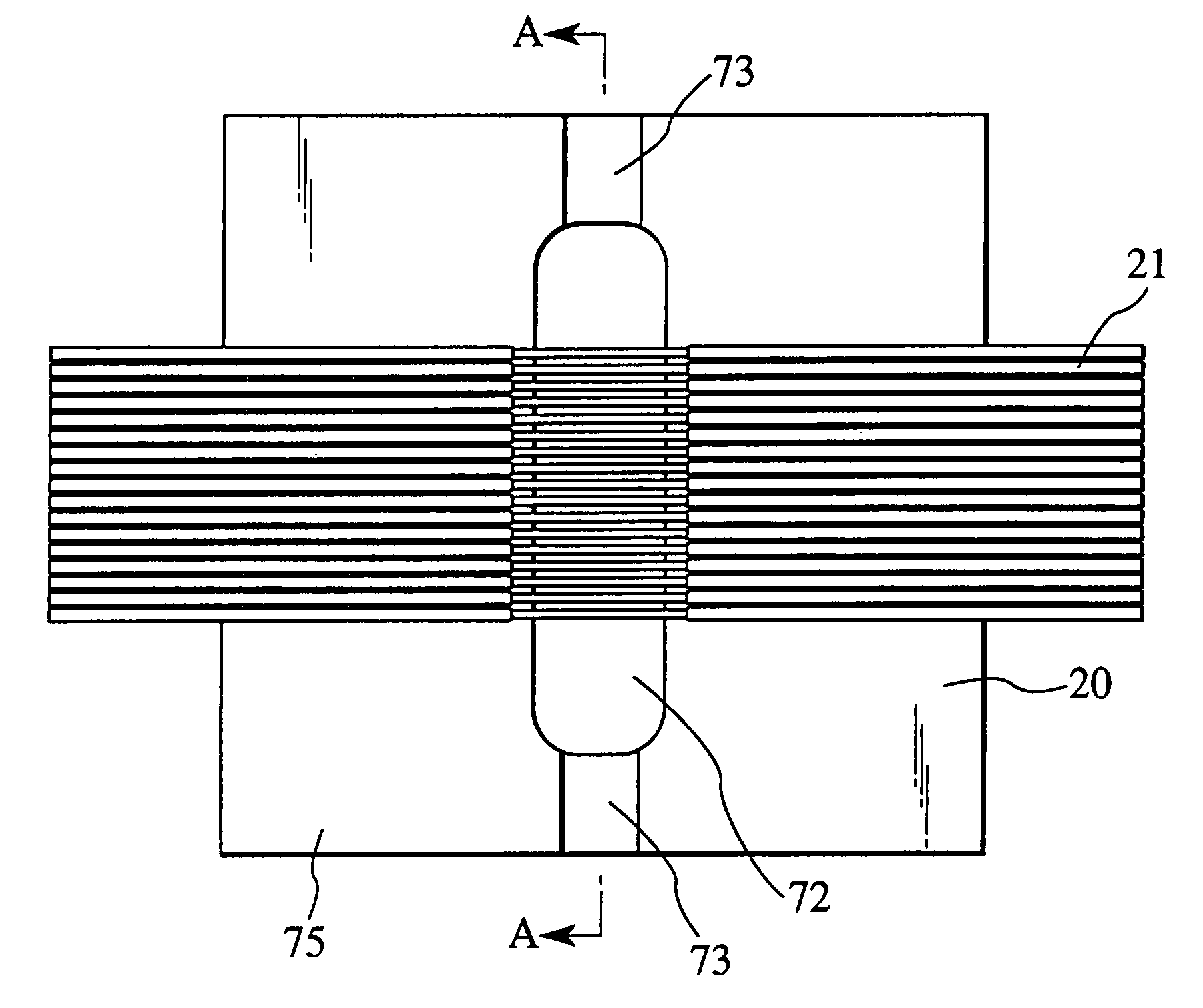
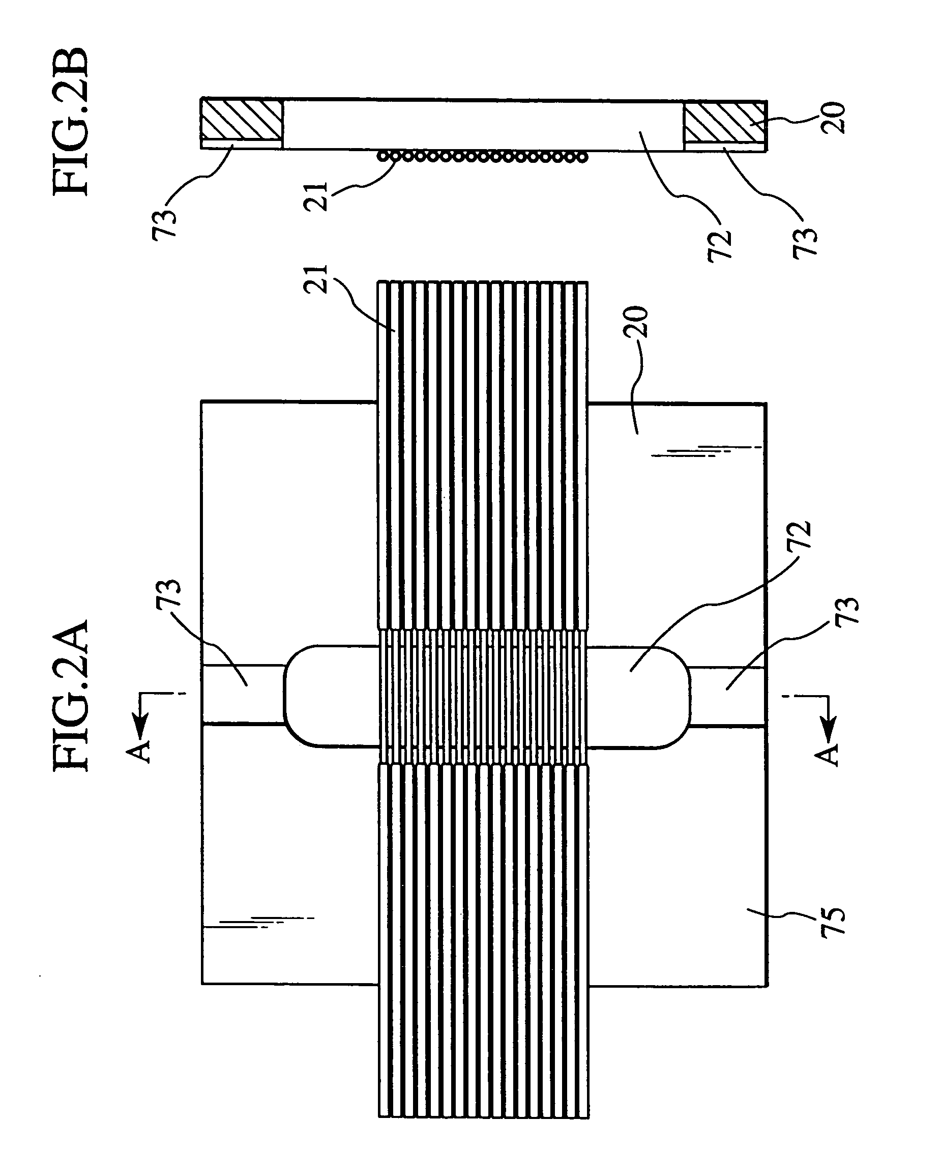
[0054]A third embodiment will be described with reference to FIGS. 12A and 12B. FIG. 12A is a front view of a part of a capillary array fixed on a planar glass substrate, and FIG. 12B is a sectional view taken along the line A—A of FIG. 12A.

[0055]Conventionally, the groove 62 has been formed along the light path of laser beams on the planar glass substrate 70 in order to avoid contact of the laser beam with the planar glass substrate 70 as described with reference to FIG. 8. The glass surface 63 corresponding to a part of the groove has been in the state of a frosted glass due to the grooving. In turn, in the present embodiment, grooves 90 for avoiding contact of the laser beams with the planar glass substrate 91 are respectively formed on opposite ends of a planar glass substrate 91, but not in an area in which capillaries 92 are aligned.

[0056]There will be explained reasons for the sufficient avoidance of contact of the laser beams with the planar glass substrate 91 that is achiev...


PUM

PropertyMeasurementUnit
outer diameteraaaaaaaaaa

Abstract

A multi-focus capillary array that can reduce crosstalk and a capillary array photodetector are provided. On a substrate 20 on which a plurality of capillaries are aligned, a perforation 72 is formed in at least a part of an area in the rear of the capillaries when the capillary array is viewed from the photodetector.

Description

CROSS-REFERENCE TO RELATED APPLICATION[0001]The present application is a continuation application of U.S. patent application Ser. No. 10 / 098,330, filed on Mar. 18, 2002 now abandoned, the disclosure of which is incorporated by reference herein.BACKGROUND OF THE INVENTION[0002]The present invention relates to a capillary array electrophoresis device for separating a sample such as fluorescence labeled DNA and detecting, identifying and analyzing a base sequence, a base length and so on of the sample according to electrophoresis in a capillary, and more particularly, to a capillary array to be incorporated into the capillary array electrophoresis device and a capillary array photodetector for detecting emission from the sample migrating through the capillary array.[0003]Capillary electrophoresis has been utilized for determination of DNA base sequences and DNA base lengths. In the capillary electrophoresis, a sample containing DNA as a measuring object is injected into a capillary mad...

Claims


Application Information

Patent Timeline
Patent Type & Authority Patents(United States)
IPC IPC(8): G01N21/00C02F1/40G01N21/64G01N27/447
CPCG01N27/44782G01N27/44721
Inventor INABA, RYOJIKITA, TOSHIAKIOZAWA, MIHOMORIOKA, TOMONARISUZUKI, AKIHIROSHIMIZU, YASUSHIKOJIMA, MASAYA
Owner HITACHI LTD
Features
  • R&D
  • Intellectual Property
  • Life Sciences
  • Materials
  • Tech Scout
  • Unparalleled Data Quality
  • Higher Quality Content
  • 60% Fewer Hallucinations
Learn More