Emission control system for vehicles powered by diesel engines

Inactive Publication Date: 2006-06-06
ENGELHARD CORP
View PDF45 Cites 97 Cited by
  • Summary
  • Abstract
  • Description
  • Claims
  • Application Information

AI Technical Summary

Benefits of technology

[0096]It is known that the adsorption/desorption characteristics of NOx adsorption sites in the NOx adsorber catalyst varies as the catalyst trap becomes saturated. If the catalyst is completely purged, the initial NOx storage sites in the catalyst have a strong affinity for storing NOx and do not readily desorb NOx. The converse is true for the last to fill NOx adsorption sites. If the catalyst is NOx saturated at the beginning of regeneration, many sites will release NOx and not all the NOx that is released will be reduced to nitrogen. That is, a burst of NOx will be produced at the onset of regeneration which will abate during regeneration. One plausible theory is that there is insufficient reductant quantity to cause reduction of all the NOx initially released during regeneration. If the regeneration occurs before NOx saturation (for example at 70% of saturation), NOx break through is diminished and the overall NOx efficiency increased.
[0097]Therefore, if the actuator(s) or engine control techniques can produce the desired rich exhaust gas composition without adversely affecting driveability, the rich/lean regeneration should stay continuously active when actuated. However, because of the separate cylinder bank control feature of the invention, there is diminished con

Problems solved by technology

However, the emissions in the diesel exhaust are characterized by relatively high emissions of nitrogen oxides (NOx) and particulates.
Additionally there is a potential for the emission gases to produce the toxic sulfuric acid, H2S, in the event of “slip”.
The problem of reductant slip is even more severe when the NOx adsorber catalyst is regenerated from adsorbed sulfur oxides (SOx).
Together with the prerequisite for effective NOx reduction, i.e. lambda<1 over the NOx adsorber catalyst, dosage of the right amount of reductants during the rich NOx adsorber regeneration poses a potential control issue.
It must be recognized, however, that the 3-way

Method used


Image

  • Emission control system for vehicles powered by diesel engines
  • Emission control system for vehicles powered by diesel engines
  • Emission control system for vehicles powered by diesel engines

Examples


Example

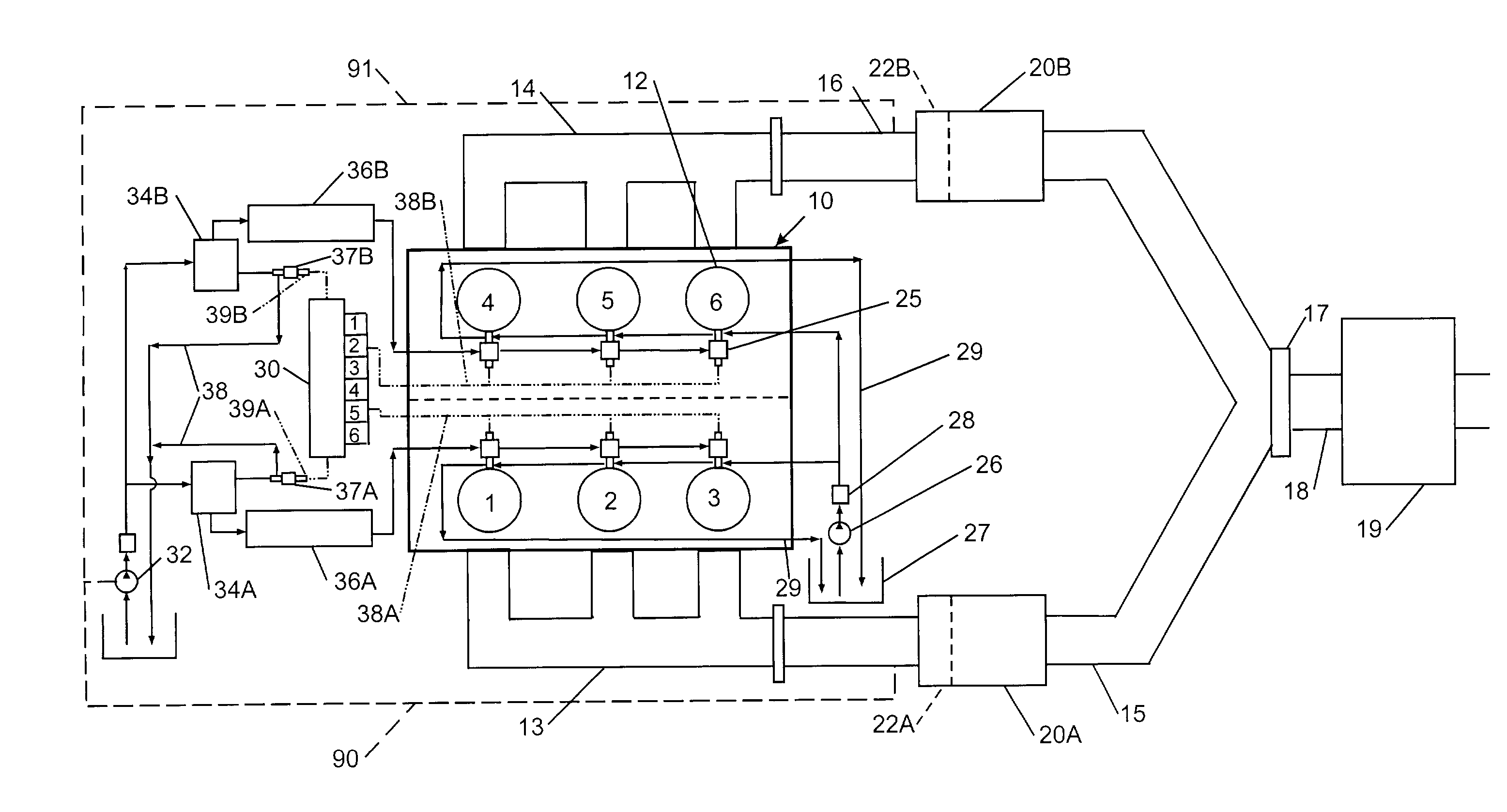
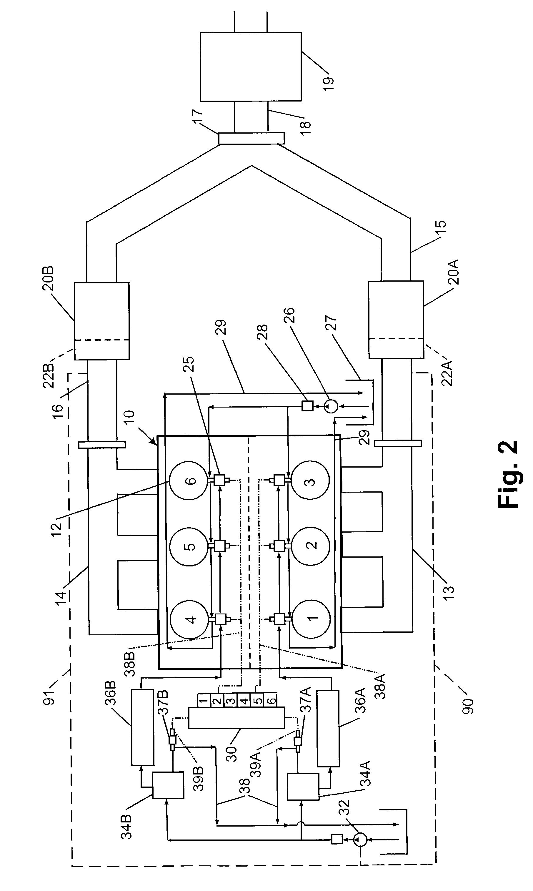
[0048]Referring now to the drawings wherein the showings are only for the purpose of disclosing a preferred embodiment of the invention and not necessarily for limiting the same, there is shown in FIG. 2 one schematic representation of a preferred embodiment of the inventive emission control system. In FIG. 2 there is depicted a multi-cylinder diesel engine 10 having two banks or pluralities of cylinders 12, with each cylinder bank exhausting products of combustion to an exhaust manifold 13, 14. For FIG. 2 cylinders 1, 2 and 3 make up the “first” or “A” cylinder bank and exhaust their combustion products into first exhaust manifold 13 and cylinders 4, 5 and 6 make up the “second” or “B” cylinder bank and exhaust their products of combustion into second exhaust manifold 14. First exhaust manifold 13 is in fluid communication with a first exhaust leg 15 and second exhaust manifold 14 is in fluid communication with a second exhaust leg 16. Each exhaust leg 15, 16 communicates with an i...


PUM


Abstract

An NOx emission system for diesel powered vehicles has a “Y” exhaust system with an NOx adsorber catalyst in each leg and an oxidation catalyst in the combined leg. One bank of cylinders sends exhaust gases to one of the “Y” legs while a second bank of cylinders send exhaust gases to the other “Y” leg. Composition of the exhaust gases in each leg is independently controlled by the engine's ECU so that exhaust gases in one leg are rich for regenerating the NOx adsorber catalyst in that leg while exhaust gas composition in the other leg is lean so that the combined gas stream is always lean and reductant slip is oxidized in the oxidation catalyst.

Description

[0001]This invention relates generally to an emission control system for a diesel engine and more particularly to an engine, equipped with an emission system for purifying the engine exhaust gases, that is operated to insure optimal functioning of the emission system.[0002]The invention is particularly applicable to and will be described with specific reference to diesel engines which typically operate at high A / F (air to fuel) ratios. However, those skilled in the art will recognize that the invention may have broader application and conceptually may have application to other internal combustion engines, such as lean burn gasoline fueled engines.BACKGROUND[0003]It is well known that compression ignition diesel engines have desirable advantages as power sources for vehicles because of their inherent high thermal efficiency (i.e., good fuel economy) and high torque at low speed. Diesel engines operate at high A / F ratios under very lean fuel conditions. As a result, diesel engines hav...

Claims


Application Information

Patent Timeline
IPC IPC(8): F01N3/00F02D45/00B01D53/94F01N3/035F01N3/08F01N3/24F01N13/02F01N13/04F02D41/00F02D41/02F02D41/04F02D41/34F02D41/36
CPCB01D53/9454F01N13/0097F01N3/035F01N3/0814F01N3/0821F01N3/0885F02D41/0082F01N13/009F01N13/011B01D53/9495F01N2510/06F01N2570/04F02D41/0275F02D2250/32Y02T10/22Y02T10/12Y02A50/20F01N3/08F02D41/02
Inventor BEUTEL, TILMAN WOLFRAMCALABRESE, JOHN LAWRENCE
Owner ENGELHARD CORP
Why Eureka
Try Eureka