Engine control system and method with lean catalyst and particulate filter
- Summary
- Abstract
- Description
- Claims
- Application Information
AI Technical Summary
Benefits of technology
Problems solved by technology
Method used
Image

Examples
Embodiment Construction
)
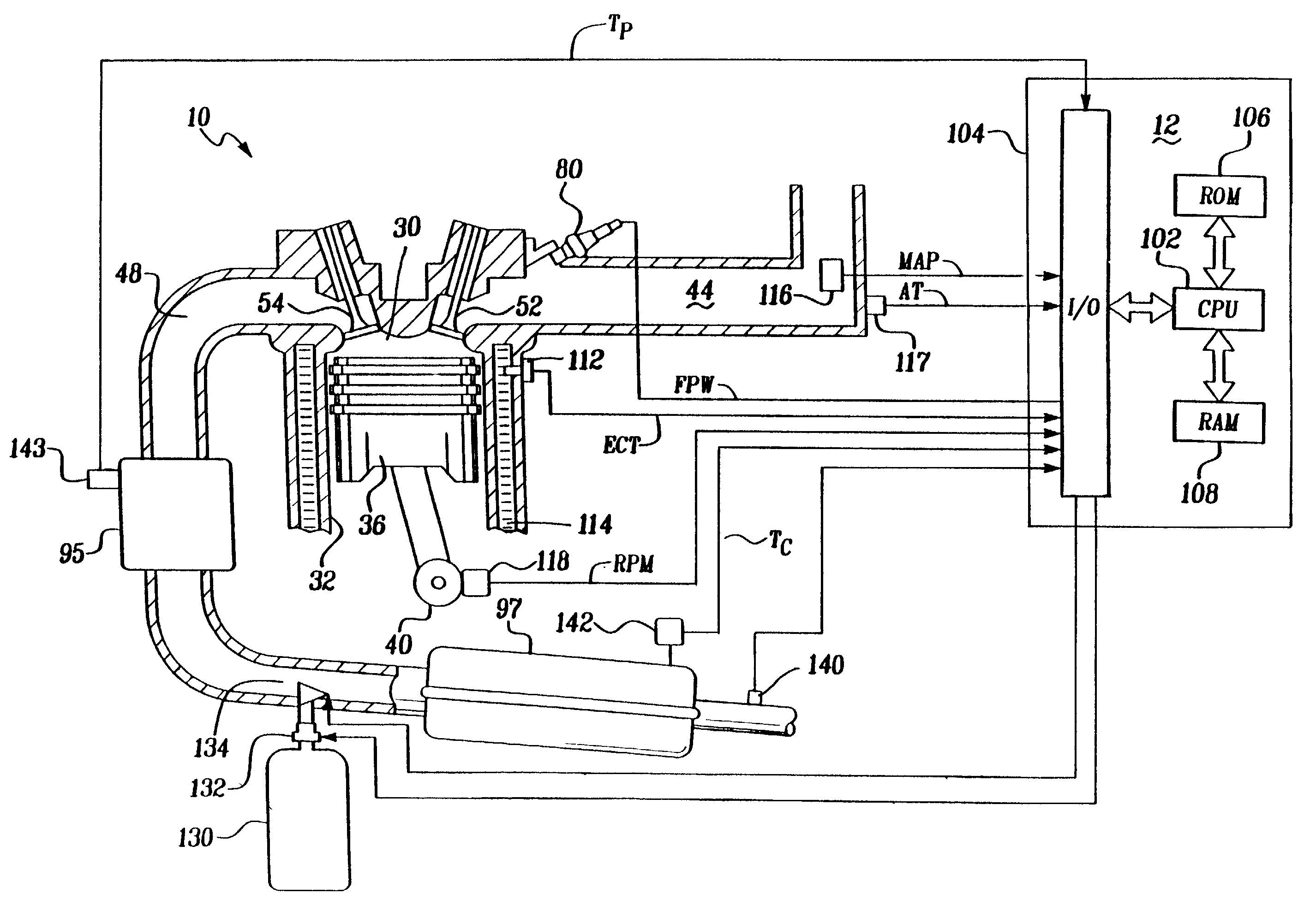
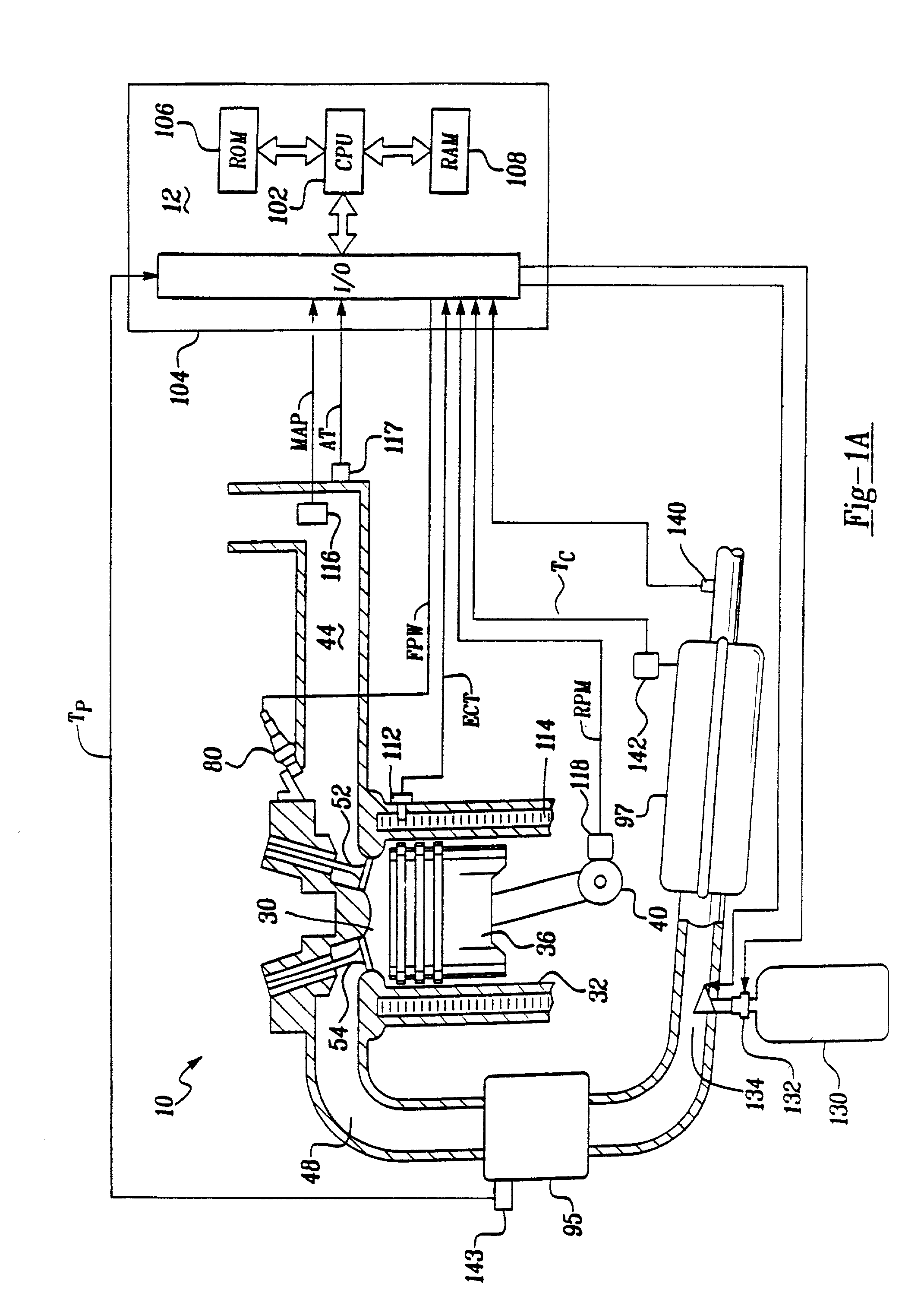
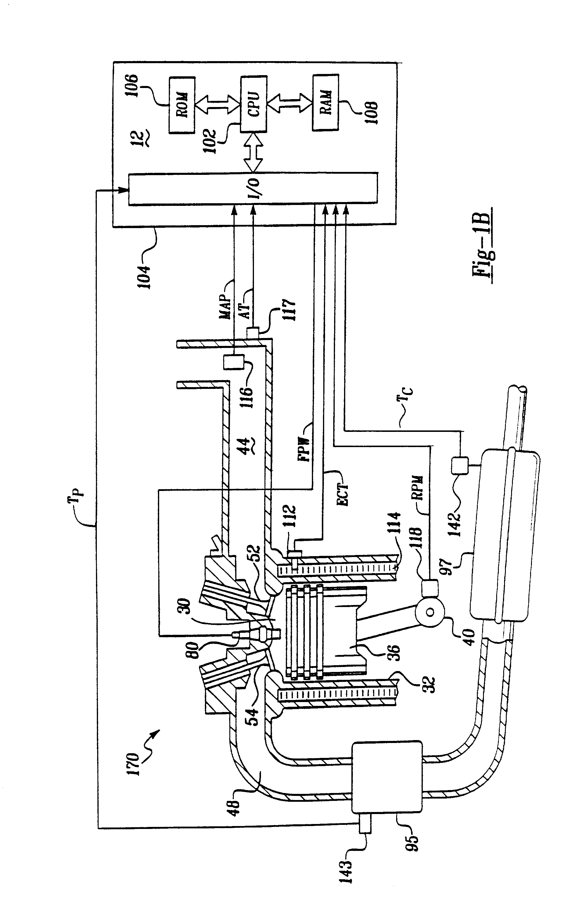
[0016]Internal combustion engine 10, comprising a plurality of cylinders, one cylinder of which is shown in FIG. 1A, is controlled by electronic engine controller 12. Engine 10 includes combustion chamber 30 and cylinder walls 32 with piston 36 positioned therein and connected to crankshaft 40. Combustion chamber 30 is known communicating with intake manifold 44 and exhaust manifold 48 via respective intake valve 52 and exhaust valve 54. Intake manifold 44 is also shown having fuel injector 80 coupled thereto for delivering liquid fuel in proportion to the pulse width of signal FPW from controller 12. Both fuel quantity, controlled by signal FPW and injection timing are adjustable. Fuel is delivered to fuel injector 80 by a diesel fuel system (not shown) including a fuel tank, fuel pump, and fuel rail (not shown). Alternatively, the engine may be configured such that the fuel is injected directly into the cylinder of the engine, which is known to those skilled in the art as a direc...
PUM
 Abstract
Description
Claims
Application Information
 - Generate Ideas
- Intellectual Property
- Life Sciences
- Materials
- Tech Scout
- Unparalleled Data Quality
- Higher Quality Content
- 60% Fewer Hallucinations
Browse by: Latest US Patents, China's latest patents, Technical Efficacy Thesaurus, Application Domain, Technology Topic, Popular Technical Reports.
© 2025 PatSnap. All rights reserved.Legal|Privacy policy|Modern Slavery Act Transparency Statement|Sitemap|About US| Contact US: help@patsnap.com