Multichannel optical communication system and method utilizing wavelength and coherence division multiplexing

Inactive Publication Date: 2006-06-13
FUTUREWEI TECH INC
View PDF8 Cites 14 Cited by
  • Summary
  • Abstract
  • Description
  • Claims
  • Application Information

AI Technical Summary

Benefits of technology

[0012]It is yet another significant advantage of the method and system of the present invention that the overall count of transmission channels is substantially increased, and the number of CDM channels added or dropped can be varied without changing the WDM physical infrastructure.
[0013]It is still another important advantage of the present invention that it utilizes a specially designed broadband optical source characterized by substantial noise reduction compared to the conventional broadband source used in the conventional CDM communication systems.
[0014]The invention provides a multichannel optical communication system for transmitting optical signals via an optical fiber. The system comprises a plurality of individual WDM transmission channels. A desired number of individual WDM transmission channels of this plurality is selected for transmission of WDM optical signals. Each WDM optical signal is transmitted via respective WDM transmission channel on a unique wavelength within a designated bandwidth. At least one WDM channel is assigned to transmit CDM optical signals. For CDM transmission, a CDM transmission unit is disposed within this at least one WDM transmission channel. The CDM transmission unit comprises one or more CDM transmission channels for transmitting CDM optical signals within the designated bandwidth of assigned at least one individual WDM transmission channel.
[0015]A broadband optical source significantly different from conventional broadband sources is used for transmitting CDM optical signals within one WDM transmission channel. According to one embodiment of the present invention a broadband optical source ha

Problems solved by technology

WDM communication systems though significantly enhancing capacity of communication networks have certain technical limitations.
Beyond these technological difficulties, there are principal limitations, such as nonlinear effects and optical dispersion.
Nonlinear effects in the optical link, particularly four-wave mixing, cause channel cross-talk and lead to significant performance degradation for the overall system.
In some

Method used


Image

  • Multichannel optical communication system and method utilizing wavelength and coherence division multiplexing
  • Multichannel optical communication system and method utilizing wavelength and coherence division multiplexing
  • Multichannel optical communication system and method utilizing wavelength and coherence division multiplexing

Examples


Embodiment Construction

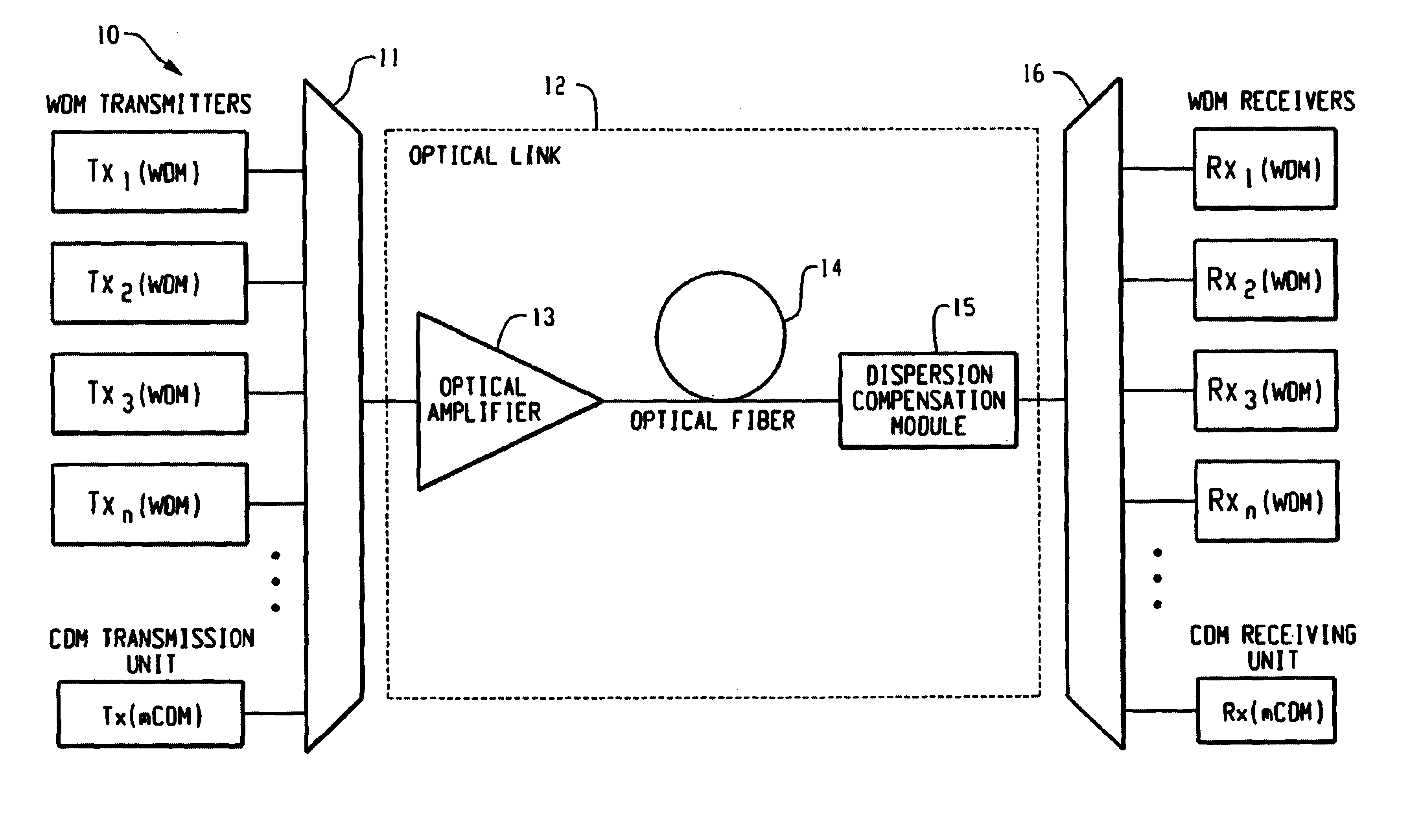
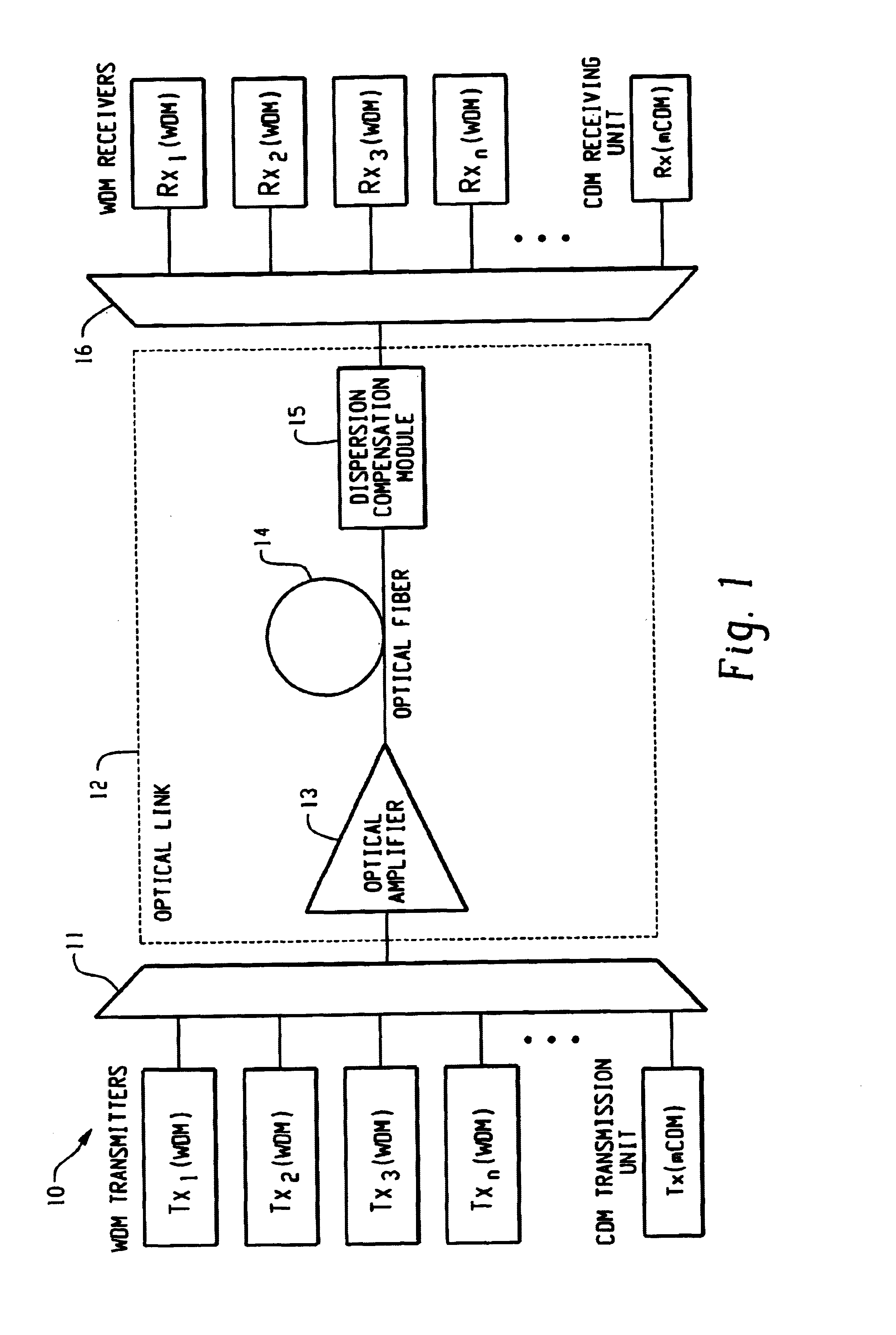
[0031]The general overview of the optical communication system of the present invention is illustrated in FIG.1 and is labeled by the reference numeral 10. The optical communication system 10 comprises a plurality of WDM transmitters Txn(WDM), and at least one CDM transmission unit Tx(mCDM), wherein n is a number of WDM transmission channels, m is a number of CMD transmission channels. Each WDM transmitter has a single transmission channel, while CDM transmission unit incorporates one or more transmission channels. Each WDM transmitter transmits the optical signal on a designated unique wavelength through an individual WDM transmission channel assigned to the designated range of wavelengths. Each CDM transmission unit transmits, within the range of wavelengths assigned to the individual WDM transmission channel, one or several CDM transmission channels.

[0032]The outputs of individual CDM transmission channels are multiplexed by CDM multiplexer (not shown) into an output of CDM trans...


PUM


Abstract

Method and system thereof for transmission of several coherence division multiplexed (CDM) optical signals via one wavelength division multiplexed (WDM) transmission channel of a multichannel WDM telecommunication system to extend the network capacity to a theoretical limit. A broadband optical source generates light within the spectral range of at least one WDM transmission channel. Several CDM channels share this spectral range to transmit and detect phase modulated optical signals through optical fiber links.

Description

FIELD OF THE INVENTION[0001]The present invention relates to transmission of optical signals over an optical fiber and, more particularly, to an optical communication method and system for transmitting several coherence division multiplexed (CDM) optical signals within one channel of wavelength division multiplexed (WDM) system to extend network capacity.BACKGROUND OF THE INVENTION[0002]Conventional optical fiber communications systems employ optical fibers to transport information in optical telecommunication networks. An electrical signal carrying information is used to modulate the light emitted by an optical source, typically a laser diode. The modulated light is then propagated through an optical fiber link comprising, in modern systems, at least one erbium-doped fiber amplifier (EDFA) and, in some systems, dispersion compensation modules (DCM). The light emerging from the optical fiber link illuminates an optical detector converting the information encoded on the optical signa...

Claims


Application Information

Patent Timeline
IPC IPC(8): H04J14/02H04B10/00H04B10/04H04J14/08H04J14/00
CPCH04J14/02H04J14/002
Inventor FISHMAN, ILYA M.BAI, YU SHENGSNEH, ANAT Z.ZAKHARENKOV, YURI A.MAURER, GREGORY S.
Owner FUTUREWEI TECH INC
Why Eureka
Try Eureka