Coating method and coated devices

a coating method and coating technology, applied in the field of ceramic coating deposition methods, can solve the problems of high temperature required in the process, inability to deposit films around corners, and said methods require advanced deposition equipment, and achieve the effect of improving biocompatibility and low temperatur

Active Publication Date: 2006-07-11
DOXA AB
View PDF7 Cites 11 Cited by
  • Summary
  • Abstract
  • Description
  • Claims
  • Application Information

AI Technical Summary

Benefits of technology

[0016]One advantage with the method is that it is a low temperature process, it can be used to deposit ceramic coatings on temperature sensitive substrates.
[0017]Another advantage is that the coated device has improved biocompatibility, particularly in contact with bone.
[0018]Still another advantage is that the coating, again due to the low temperature deposition process, may be used as binder-material for biocompatible materials such as hydroxyapatites and calcium carbonates, without altering their micro-structure or chemical composition, i.e. the exact biological properties is kept after deposition.
[0019]Furthermore, due to the simplicity of the method, deposition of coatings on selected sections of a substrate is possible. Also implants may be coated in a quick and simple way prior to the implant procedure.

Problems solved by technology

Contrary to CVD, PVD processes are line of sight processes, which imply that it is not possible to deposit films around corners, inside tubes, etc.
A disadvantage with existing techniques for deposition of ceramic films is the elevated temperatures required in the process.
Therefore, the most preferred of the above methods is often PVD, which may be used for deposition around 300° C. Another disadvantage is that said methods require advanced deposition equipment, especially CVD and PVD, for which gas-tight vacuum-arrangements are needed.
The main disadvantage with thermal spray deposition is the temperatures of the melting zone.
Cooling from typically 10 000° C. to room temperature in a few microseconds, implies that possibilities to control the micro-structure of the coating are very limited.
As pure bulk material hydroxyapatites and other calcium phosphates have poor mechanical properties.
However, all techniques involving elevated temperatures tend to alter the microstructure of the hydroxyapatite, e.g. that the hydration water in the hydroxyapatites leaves the structure.
However, the limited mechanical properties of these materials set limitations to their use.

Method used


Image

  • Coating method and coated devices
  • Coating method and coated devices
  • Coating method and coated devices

Examples


example

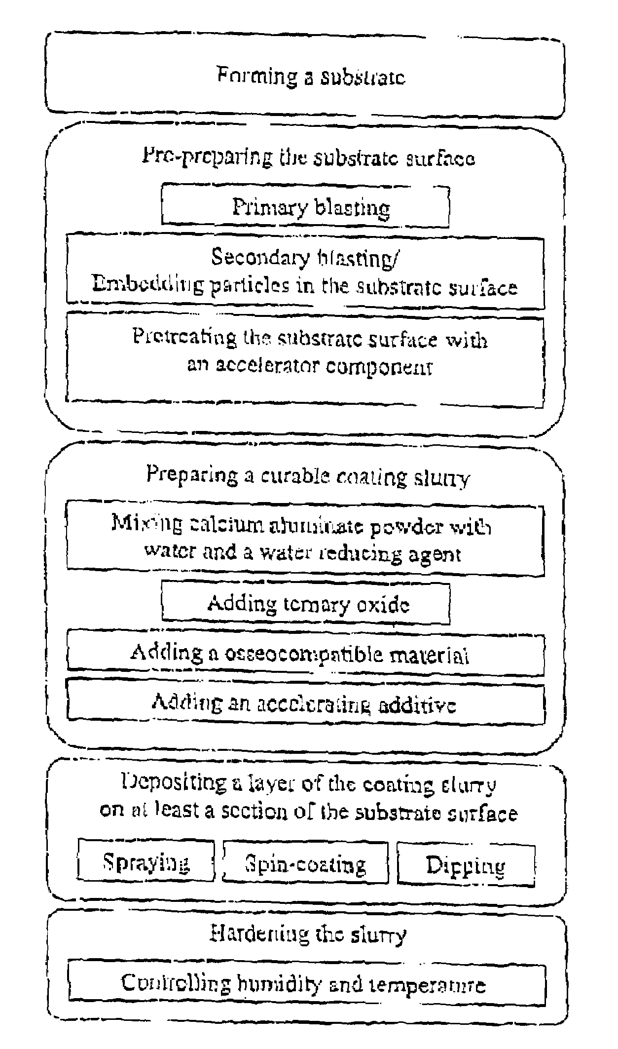
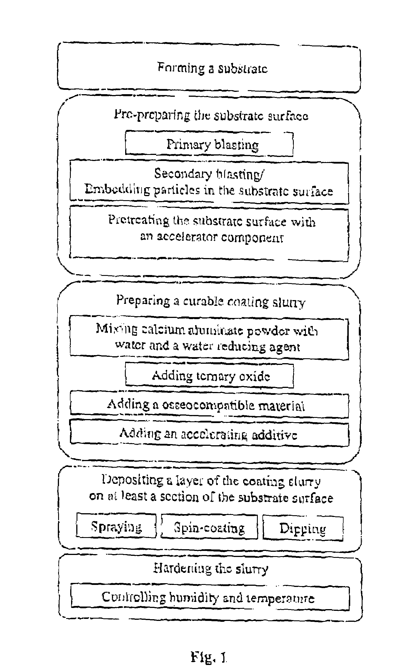
[0073]This non-limiting example describes one embodiment of the surface coating method according to the invention more in detail, and the mechanical properties of these coatings.

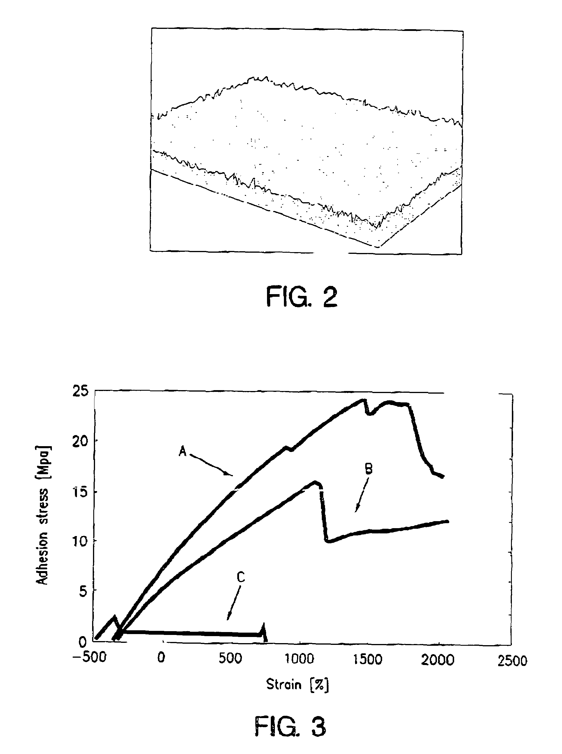
[0074]In this example, round bars of pure medical grade titanium, ASTM Gr.2, with a diameter of 6 mm, were used substrates. The titanium bars was pretreated with wet blasting using aluminum oxide grit with a particle size of 100–120 mesh. The blasting was performed with a pressure of 1 bar (air pressure). After blasting, the surface roughness and morphology was characterized using Scanning Electron Microscopy (SEM) and optical profilometry (OP). The surface roughness was shown to be in the range of Ra=0.6–0.7 μm after wet blasting, see FIG. 2.

[0075]To improve the bonding between the titanium and the coating, a secondary blasting of the metal surfaces was performed using calcium aluminate (CA) particles with a grit size between 0 and 22 μm (90%) at a pressure of ˜10 bar (air pressure). The resulting surface m...


PUM

PropertyMeasurementUnit
Raaaaaaaaaaa
temperatureaaaaaaaaaa

Abstract

Surface coating method for deposition of a chemically bonded ceramic coating on a substrate, includes the steps of preparing a curable coating slurry, depositing a coating of the slurry on at least a section of the substrate surface, and hardening the slurry. The step of preparing a curable coating slurry includes mixing calcium aluminate powder with water and at least one water-reducing-agent, such that a water-to-cement ratio in the range of 0.1 to 0.9 is achieved.

Description

THE FIELD OF THE INVENTION[0001]The present invention relates to a method for deposition of ceramic coatings, a biocompatible surface coating and devices coated with said biocompatible surface coating, and in particular to a method for deposition of ceramic coatings having a high degree of biocompatibility and medical devices for implantation, comprising a substrate that is coated with such a biocompatible ceramic layer.BACKGROUND OF THE INVENTIONSurface Coating Techniques[0002]A vast variety of materials can be deposited as thin films or coatings. This invention particularly focuses on ceramic coatings. Ceramic coatings are often used for properties like, hardness, friction, corrosion resistance, and biocompatibility.[0003]The most established techniques for depositing ceramic of coatings are CVD (Chemical Vapor Deposition), PVD (Physical Vapor Deposition), electrolytic deposition, and thermal spray deposition. Furthermore, there are numerous subgroups within each deposition techni...

Claims


Application Information

Patent Timeline
Patent Type & Authority Patents(United States)
IPC IPC(8): A61B17/00B05D1/12A61B17/58A61F2/30A61F2/44A61L27/00A61L27/30A61L31/08C04B22/06C04B22/10C04B22/16C04B28/06C04B41/85C23C4/10C23C10/18C23C24/08C23C26/00
CPCA61L27/30C23C24/08C23C10/18A61L31/082
Inventor AXEN, NIKLASHERMANSSON, LEIFJOHANSSON, ERIKPERSSON, TOBIAS
Owner DOXA AB
Why Eureka
Try Eureka