
Porcelain composition for varistor and varistor

a technology of varistors and porcelain, which is applied in the direction of superconductor devices, electrical appliances, basic electric elements, etc., can solve the problems of increasing prone to evaporate, and difficult to decrease the variation in grain diameter, etc., to achieve small leak current, high surge resistance, and large esd resistance

Inactive Publication Date: 2006-07-11
MURATA MFG CO LTD
View PDF11 Cites 23 Cited by
  • Summary
  • Abstract
  • Description
  • Claims
  • Application Information

AI Technical Summary

Benefits of technology

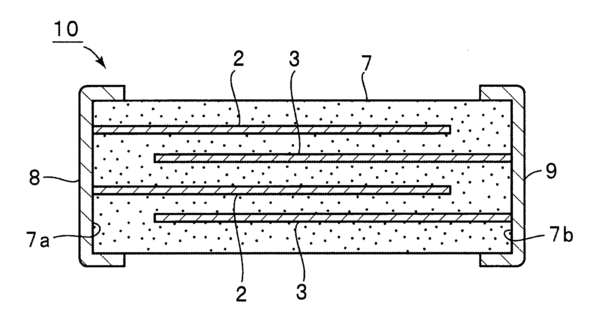
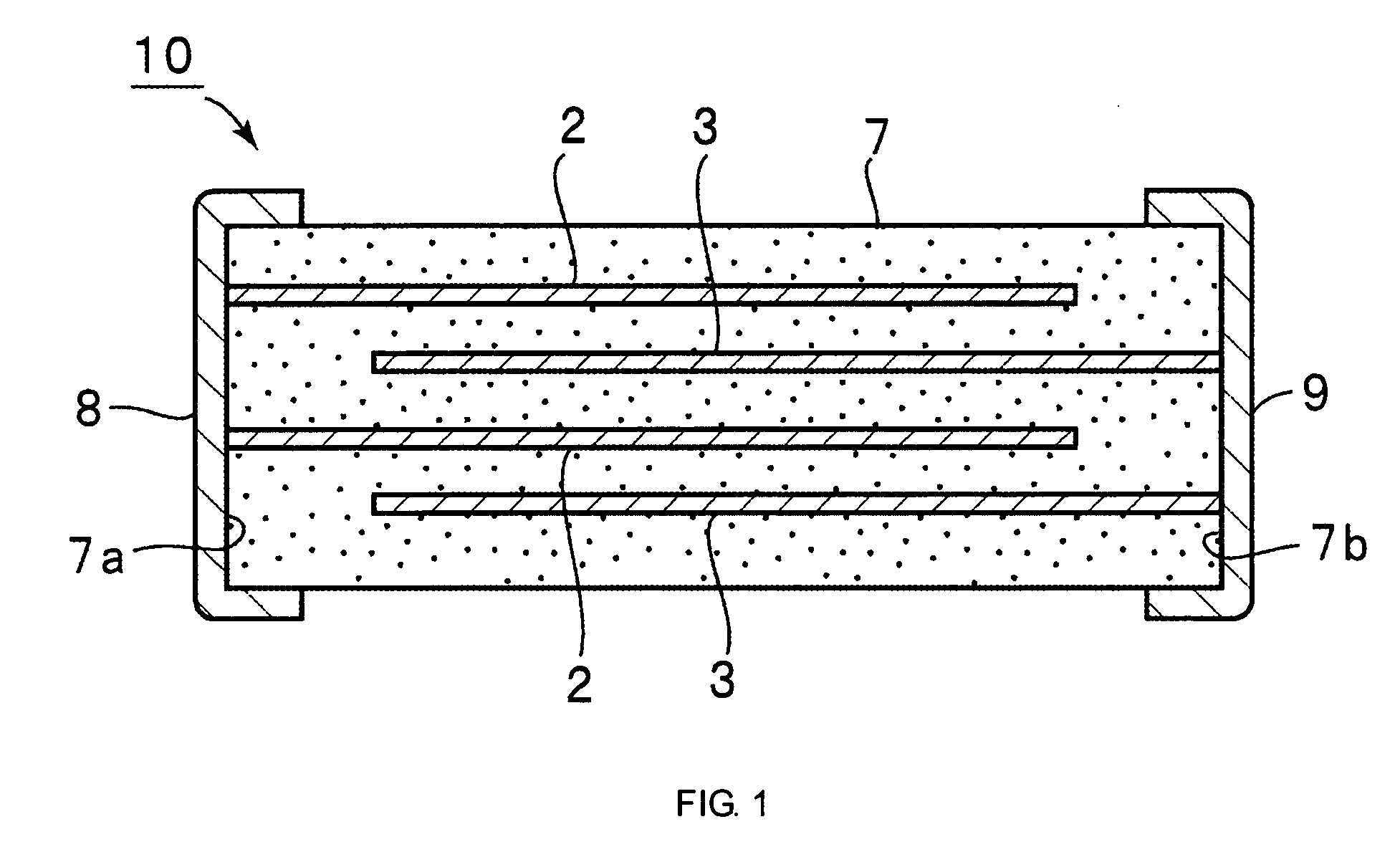
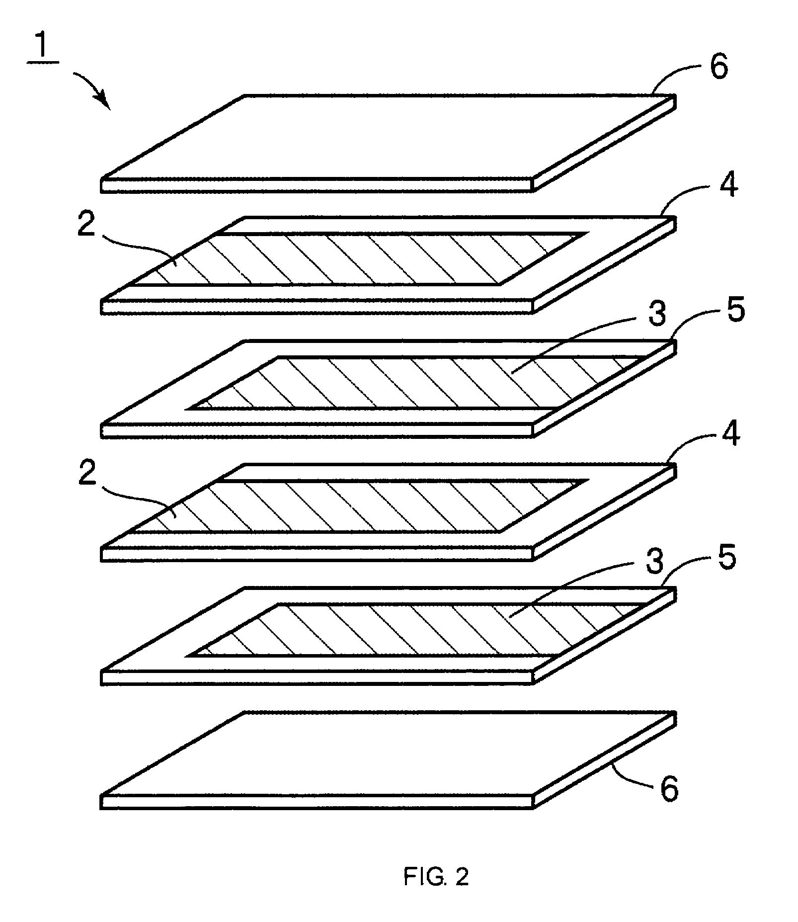
[0015]A varistor of the present invention comprises a sintered body and a plurality of terminal electrodes formed on exterior surfaces of the sintered body, the sintered body having a ceramic composition which is used for forming a varistor and which has the above specific composition. The structure thereof is not particularly limited. That is, there may be provided a monolayer varistor composed of a monolayer varistor substrate of the sintered body described above and exterior electrodes provided on two surfaces thereof. However, in accordance with one specific aspect of the present invention, in the sintered body described above, a plurality of interior electrodes is formed to be laminated to each other with sintered body layers provided therebetween, and the interior electrodes mentioned above are electrically connected to respective exterior electrodes, thereby forming a multilayer varistor. Hence, in particular, a multilayer varistor can be provided which can be driven at a low voltage, such as at a rated voltage of 30 V or less, and which has a small leak current, a high surge resistance, a sufficiently large ESD resistance, and superior reliability.

Problems solved by technology

On the other hand, in the method for increasing the grain diameter, the growth of grains must be facilitated, and hence abnormal growth of grains is liable to occur, thereby increasing the variation in grain diameter.
However, in firing, Bi2O3 or Sb2O3 having a low melting point tended to form a liquid phase and was also liable to evaporate.
As a result, it was difficult to decrease the variation in grain diameter.
Consequently, it has been difficult to stably manufacture and supply multilayer varistors which can be driven at a lower voltage and which has superior reliability.
In addition, since the variation in grain diameter was liable to increase, a surge current or ESD was concentrated at positions at which grains having a large grain diameter were present, and the resistances against surge current and ESD were also liable to decrease.
However, as compared to the varistor material containing a Bi base sub-component, the varistor material containing a Pr base sub-component had a problem of a large leak current.
Hence, there have been problems in that the power consumption is increased and that the malfunction of signal circuits occurs.
However, when the methods described above are used, the surge resistant is significantly decreased.
When a conventional varistor material containing a Pr base sub-component is used, in a multilayer chip type varistor which can be driven at a low voltage of 30 V or less, it has been difficult to suppress the leak current and to realize a high surge resistance.
However, since Bi2O3 tends to form a liquid phase at a low temperature or is liable to evaporate, it has been difficult to obtain uniform particle diameters.
In addition, it has also been difficult to stably supply a voltage non-linear resistor which has superior reliability and which can be driven at a low voltage.

Method used


Image

  • Porcelain composition for varistor and varistor
  • Porcelain composition for varistor and varistor
  • Porcelain composition for varistor and varistor

Examples


example 1

[0035]In Example 1, among Pr, Co, K, Al, and Zr used as a sub-component, samples in which the content of Pr was primarily changed were formed, and the properties thereof were evaluated.

[0036]First, ZnO, Pr6O11, CoO, K2CO3, Al2O3, and ZrO2 powders used as starting materials were weighed so that a ceramic sintered body after firing had a predetermined composition and were then wet-mixed by a ball mill for 24 hours, thereby forming a mixed slurry. After dehydrated and dried, the mixed slurry was calcined at a temperature of 700 to 1,100° C. for 2 hours in the air, thereby forming a calcined raw material. The calcined raw material thus obtained was again sufficiently pulverized using a ball mill, and subsequently, dehydration and drying were performed. An organic binder, an organic plasticizer, and a dispersing agent were added to the raw material thus dried, and a mixture thus formed was mixed for 12 hours using a ball mill, thereby forming a slurry.

[0037]The slurry thus formed was pro...

example 2

[0049]In Example 2, among Pr, Co, K, Al, and Zr used as a sub-component, samples in which the content of Co was primarily changed were formed, and the properties thereof were evaluated.

[0050]Except that the contents of the sub-components were changed as shown in the following Table 2, multilayer varistors were formed in the same manner as that in Example 1, and the evaluation was performed. The results are shown in Table 2 below.

[0051]

TABLE 2SURGEESDSAMPLEADDITION ELEMENT (atom %)VARISTORRESIS-RESIS-NO.PrCoKAlZrINITIAL IRVOLTAGETANCETANCE*250.30.10.051 × 10−40.10.04MΩ9.1 V15 A2kV*260.30.30.051 × 10−40.10.5MΩ9.0 V18 A5kV270.30.50.051 × 10−40.11.0MΩ8.8 V20 A30kV280.310.051 × 10−40.11.6MΩ8.9 V20 A30kV290.320.051 × 10−40.11.8MΩ9.4 V25 A30kV300.340.051 × 10−40.12.5MΩ9.1 V21 A30kV310.350.051 × 10−40.12.7MΩ9.2 V21 A30kV320.380.051 × 10−40.13.2MΩ9.0 V20 A30kV330.3100.051 × 10−40.14.1MΩ8.9 V20 A30kV*340.3120.051 × 10−40.16.0MΩ8.8 V18 A15kV350.30.50.51 × 10−40.12.3MΩ8.8 V21 A30kV360.3100.0051...

example 3

[0055]In Example 3, among Pr, Co, K, Al, and Zr used as a sub-component, samples in which the content of K was primarily changed were formed, and the properties thereof were evaluated.

[0056]Except that the contents of the sub-components were changed as shown in the following Table 2, multilayer varistors were formed in the same manner as that in Example 1, and the evaluation was performed. The results are shown in Table 3 below.

[0057]

TABLE 3SURGEESDSAMPLEADDITION ELEMENT (atom %)VARISTORRESIS-RESIS-NO.PrCoKAlZrINITIAL IRVOLTAGETANCETANCE*440.32.001 × 10−40.10.001MΩ8.7 V30 A30kV*450.32.00.0011 × 10−40.10.02MΩ8.9 V29 A30kV*460.32.00.0031 × 10−40.10.4MΩ9.2 V29 A30kV470.32.00.0051 × 10−40.11.0MΩ9.0 V27 A30kV480.32.00.011 × 10−40.11.4MΩ9.2 V26 A30kV490.32.00.051 × 10−40.11.8MΩ9.4 V25 A30kV500.32.00.081 × 10−40.12.2MΩ8.9 V25 A30kV510.32.00.11 × 10−40.12.9MΩ9.0 V24 A30kV520.32.00.31 × 10−40.13.2MΩ9.1 V20 A30kV530.32.00.51 × 10−40.13.4MΩ9.0 V20 A30kV*540.32.00.81 × 10−40.14.2MΩ8.8 V15 A15kV...


PUM

PropertyMeasurementUnit
varistor voltageaaaaaaaaaa
voltageaaaaaaaaaa

Abstract

A varistor is provided which can be driven at a low voltage, has a small leak current, and can realize a high ESD resistance and a high surge resistance. The varistor is formed using a ceramic composition for a varistor which contains zinc oxide as a primary component and sub-components including praseodymium at a content of 0.05 to 3.0 atomic percent of the total, cobalt at a content of 0.5 to 10 atom percent of the total, at least one of potassium, sodium, and lithium at a total content of 0.005 to 0.5 atom percent of the total, at least one of aluminum, gallium, and indium at a total content of 2×10⁻⁵ to 0.5 atom percent of the total, and zirconium at a content of 0.005 to 5.0 atom percent of the total.

Description

TECHNICAL FIELD[0001]The present invention relates to ceramic compositions for varistors used for electrostatic protection elements, noise filters, and the like and to the varistors, and more particularly, relates to a ceramic composition for a varistor primarily composed of ZnO and the varistor.BACKGROUND ART[0002]Heretofore, for protection against overvoltage, varistors having a monolayer sintered body primarily composed of ZnO have been widely used. In recent years, in addition to the protection against overvoltage, as electrostatic discharge (ESD) protection elements and noise filters, multilayer varistors composed of a plurality of internal electrodes disposed in a sintered body have been increasingly used.[0003]In addition, concomitant with the trend toward higher integration and lower drive voltage of electronic apparatuses such as mobile communication apparatuses and notebook personal computers, varistors have been strongly required to be stably driven at a lower rated volta...

Claims


Application Information

Patent Timeline
Patent Type & Authority Patents(United States)
IPC IPC(8): H01C7/10C04B35/453H01C7/04H01C7/112H01C17/065
CPCC04B35/453H01C17/06546C04B35/638H01C7/044H01C7/112C04B35/6262C04B2235/3201C04B2235/3203C04B2235/3208C04B2235/3213C04B2235/3215C04B2235/3217C04B2235/3224C04B2235/3225C04B2235/3227C04B2235/3244C04B2235/3275C04B2235/3284C04B2235/3286C04B2235/6025H01C7/10
Inventor HIROSE, SAKYONAKAYAMA, AKINORISHIRATSUYU, KOUSUKE
Owner MURATA MFG CO LTD
Learn More