Temperature sensing circuit

Inactive Publication Date: 2006-07-18
RICOH KK
View PDF9 Cites 20 Cited by
  • Summary
  • Abstract
  • Description
  • Claims
  • Application Information

AI Technical Summary

Benefits of technology

[0029]Thus, according to the present invention, various drawbacks of the circuits using bipolar transistors can be eliminated by since a temperature detection circuit is fabricated using CMOS transistors Thus, since MOS transistors are used, the temperature-sensing circuit of the present invention is operable with low current consumption and can be integrated into an IC chip. Further, since the circuit is arranged to obtain work function differences between a plurality of MOS transist

Problems solved by technology

Such a complicated electronic circuit results in increased cost and size of the temperature sensor system.
The above-mentioned second type temperature sensor is constructed using a bipolar transistor and thus cannot be integrated into an IC chip fabricated by a standard CMOS process.
Also, since a bipolar transistor is a current element controlled by an electric current, it is difficult to construct a circuit with a low current consumption.
Among the temp

Method used


Image

  • Temperature sensing circuit
  • Temperature sensing circuit
  • Temperature sensing circuit

Examples


Embodiment Construction

[0041]In the following, the principle and embodiments of the present invention will be described with reference to the accompanying drawings.

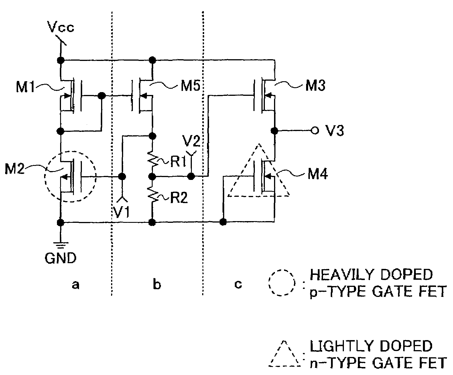
[0042]According to the present invention, MOS transistors each having a gate with a work function different from a gate of the other MOS transistor are used for achieving a temperature-sensing circuit operable at a high temperature in a CMOS process. Before explaining embodiments of the present invention, the principle of the present invention will be described.

[0043]A threshold voltage Vt for switching ON a channel of a MOS transistor (hereinafter referred to as a transistor) is given by:

Vt=φms−Qf / Cox+2φf−Qb / Cox  (1),

where, φms is the difference between work function φm of the gate and work function φs of a substrate, Qf represents fixed electric charges in an oxide film, φf represents the Fermi level of the substrate, Qb represents electric charges in a depletion layer between an inversion layer and the substrate and Cox represents capacitanc...


PUM


Abstract

A temperature-sensing circuit includes a first circuit block outputting an output voltage having negative or positive temperature coefficients and a second circuit block amplifying the output voltage of the first circuit block to a predetermined amplitude and outputting the amplified output voltage. It further includes a third circuit block producing a voltage having temperature coefficients of a polarity opposite to that of the first circuit block and adding the produced voltage to the output voltage of the second circuit block to cancel out components of second order temperature coefficients contained in the output voltages of the first and second circuit blocks.

Description

BACKGROUND OF THE INVENTION[0001]1. Field of the Invention[0002]The present invention generally relates to a temperature-sensing circuit using CMOS (complementary metal oxide semiconductor) transistors, and particularly relates to a temperature-sensing circuit capable of performing a stable operation at a high temperature, notably at a temperature above 100° C.[0003]2. Description of the Related Art[0004]There are various types of temperature sensors known in the art.[0005]A first type is a temperature sensor system making use of thermocouples or resistors. In the case of thermocouples, a thermocurrent produced at a contact point between two types of metal wires is amplified by an amplifier and measured by a voltmeter. In the case of resistors, a three-wire bridge arrangement is used such that a voltage change due to the change of resistance is amplified by an amplifier and a change of resistance value due to a change of temperature is measured by a voltmeter.[0006]A second type is ...

Claims


Application Information

Patent Timeline
IPC IPC(8): G05F3/16G01K7/01G01K7/21
CPCG01K7/21
Inventor WATANABE, HIROFUMI
Owner RICOH KK
Why Eureka
Try Eureka