
Bandwidth control technique for a laser

Inactive Publication Date: 2006-07-18
CYMER INC
View PDF32 Cites 3 Cited by
  • Summary
  • Abstract
  • Description
  • Claims
  • Application Information

AI Technical Summary

Benefits of technology

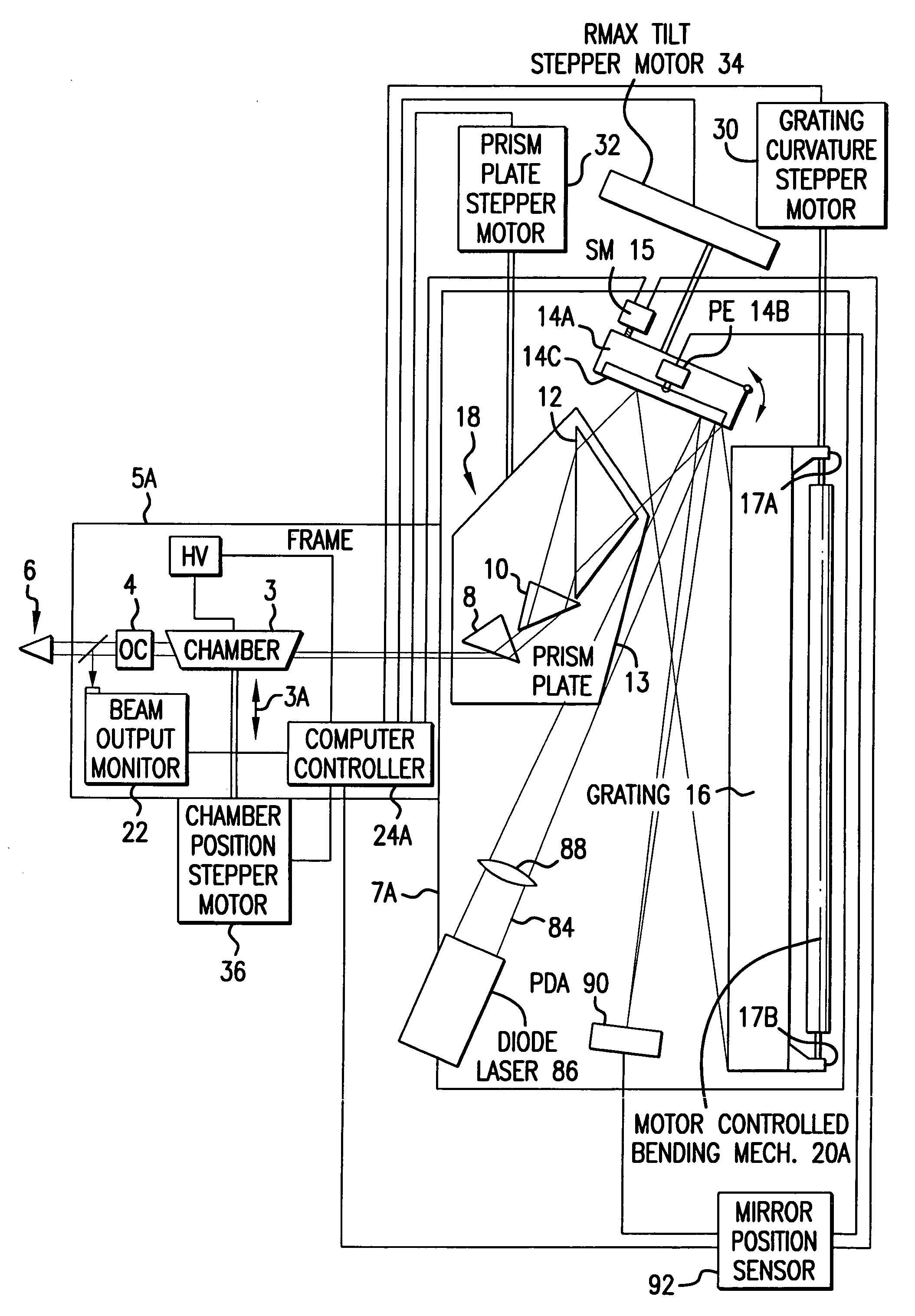
[0010]The present invention provides a technique for bandwidth control of an electric discharge laser. Line narrowing equipment is provided having at least one piezoelectric drive and a fast bandwidth detection means and a bandwidth control having a time response of less than about 2.0

Problems solved by technology

The etalon creates an interference pattern having concentric bands of dark and light levels due to destructive and constructive interference by the laser light.
The limitations of acceptable optical lens materials for use with deep ultraviolet light at 248 nm and 193 nm wavelengths have meant that projection lenses for KrF and ArF lithography have been fabricated primarily with fused silica.
Although fused silica is a very good lens material (high transparency, low thermal expansion, relatively easy to polish), the unavailability of a second material type with a different refractive index in projection lenses results in chromatic aberrations.
Nevertheless, although excimer laser bandwidths are small, the lack of chromatic correction in lenses means that the bandwidth cannot be ignored.
However, recently integrated circuit manufacturers have noticed that the quality of their integrated circuits can be adversely affected by bandwidths which are substantially narrower than the bandwidths for which their optical systems were designed.

Method used


Image

  • Bandwidth control technique for a laser
  • Bandwidth control technique for a laser
  • Bandwidth control technique for a laser

Examples


Embodiment Construction

Simulation

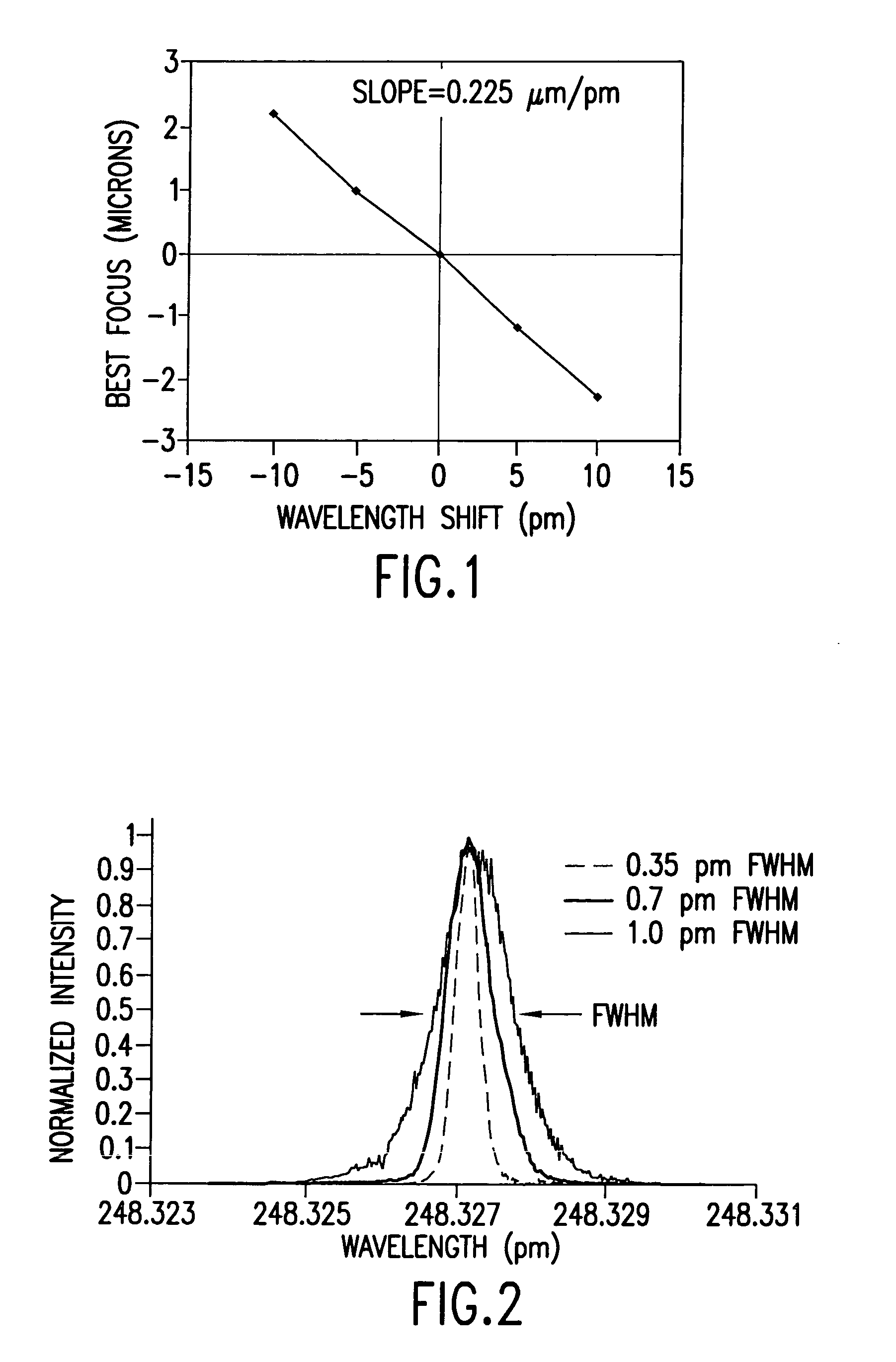
[0026]Simulation of the effects of wavelength and bandwidth changes have been performed by Applicants. The main effect of changing the exposure wavelength for a non-chromatic corrected lens is a change in the position of the focal plane. Over a fairly wide range of wavelengths, this change in focus is essentially linear with the change in the nominal wavelength (i.e., the central wavelength of the illumination spectrum). The wavelength response of a lens can be determined experimentally by manually changing the central wavelength of the laser and using the imaging sensor of the stepper to monitor the shift in focus that results. FIG. 1 shows an example of such a measurement.

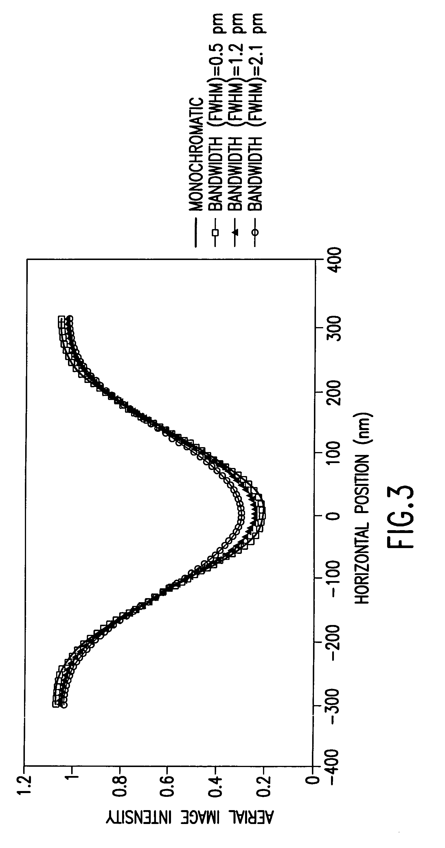
[0027]Given the change in focus with change in wavelength, the use of a broadband illumination spectrum means that each wavelength in the spectrum will produce an aerial image with a different best focus. The total aerial image will be a sum of the aerial images at each focal position, weighted by the r...


PUM


Abstract

A technique for bandwidth control of an electric discharge laser. Line narrowing equipment is provided having at least one piezoelectric drive and a fast bandwidth detection means and a bandwidth control having a time response of less than about 1.0 millisecond. In a preferred embodiment wavelength tuning mirror is dithered at dither rates of more than 500 dithers per second within a very narrow range of pivot angles to cause a dither in nominal wavelength values to produce a desired effective bandwidth of series of laser pulses.

Description

FIELD OF THE INVENTION[0001]This application is a divisional of Ser. No. 09 / 608,543 filed Jun. 30, 2000 now U.S. Pat. No. 6,721,340 which is a continuation-in-part of Ser. No. 09 / 597,812 filed Jun. 19, 2000, now U.S. Pat. No. 6,529,531 which was a continuation-in-part of Ser. No. 08 / 898,630 filed Jul. 22, 1997 now U.S. Pat. No. 6,078,599 and Ser. No. 09 / 501,160 filed Feb. 9, 2000 now U.S. Pat. No. 6,621,846. This invention relates to lasers and, in particular, to techniques for control of the bandwidth of the output beam.BACKGROUND OF THE INVENTIONWavelength Control[0002]Lasers are used for many applications. For example, lasers, such as KrF and ArF excimer lasers, are used in stepper and scanner equipment for selectively exposing photoresist in a semiconductor wafer fabrication process. In such fabrication processes, the optics in the steppers and scanners are designed for a particular wavelength of the laser. The laser wavelength may drift over time and, thus, a feedback network i...

Claims


Application Information

Patent Timeline
IPC IPC(8): H01S3/09H01S3/10G03F7/20H01S3/036H01S3/038H01S3/04H01S3/041H01S3/097H01S3/0975H01S3/104H01S3/105H01S3/1055H01S3/13H01S3/134H01S3/22H01S3/225
CPCG03F7/70025H01S3/225G03F7/70333G03F7/70575G03F7/70933H01S3/036H01S3/104H01S3/13G03F7/70041H01S3/0385H01S3/0404H01S3/041H01S3/097H01S3/0975H01S3/105H01S3/1055H01S3/134H01S3/22H01S3/2207
Inventor FOMENKOV, IGOR V.KROYAN, ARMENBUCK, JESSE D.DAS, PALASH P.SANDSTROM, RICHARD L.ERIE, FREDERICK G.ALGOTS, JOHN MARTINPADMABANDU, GAMARALALAGE G.
Owner CYMER INC
Learn More