Magnetic disk drive having a surface coating on a magnetic disk

a magnetic disk and surface coating technology, applied in the field of magnetic disk recording information, can solve the problems of increasing the rotational speed of the magnetic disk, reducing the proportion of the lubricating film bonded layer, and the process has not been effective for reducing the mobile component, so as to improve the bonding rate and the effect of strong adhesion to the underlying disk surface and high bonding ra

Inactive Publication Date: 2006-07-25
KK TOSHIBA
View PDF18 Cites 7 Cited by
  • Summary
  • Abstract
  • Description
  • Claims
  • Application Information

AI Technical Summary

Benefits of technology

[0094]According to the present invention, a lubricating film having a high bonding rate to an underlying magnetic disk surface is obtained by using a fluorocarbon resin without using polar endcap groups in the lubricating film. Because of elimination of the use of polar endcap groups, the problem of coagulation, which tends to occur in the conventional lubricating film that uses polar endcap groups in the resin, is effectively eliminated. In order to achieve a strong adherence to the underlying disk surface, the present invention uses non-polar endcap groups such that the endcap groups contain π electrons. Preferably, the non-polar endcap group contains at least eight π electrons. Because of the improved bonding rate, the lubricating film remains on the surface of the magnetic disk without lateral displacement, even in such a case the magnetic disk is rotated at a high speed. Further, the lubricating film thus formed effectively reduces the friction of the surface of the magnetic disk.

Problems solved by technology

On the other hand, such a conventional lubricating film 11F using conventional perfluoro resin compound encounters a problem in that, while the bottom part of the lubricating film 11F is thus bonded firmly upon the surface of the underlying hard carbon film 11E, the upper part of the lubrication film 11F is not bonded and forms a mobile component that can move freely over the surface of the hard carbon film 11E and hence the surface of the magnetic disk 11.
Thus, the existence of such a mobile component causes a serious problem particularly in recent high-recording-density magnetic disk drives in which the air gap formed between the magnetic disk surface and the magnetic head is reduced and the rotational speed of the magnetic disk is increased.
Thus, such a process has been not effective for reducing the mobile component.
However, there still remains difficulty to increase the proportion of the bonded layer in the lubricating film 11F in the magnetic disk of FIG. 3.
However, such a process is effective only after optical exposure conducted for a long period of time and the throughput of production of the magnetic disk drive is deteriorated substantially.
Further, there is a risk in such an optical radiation process in that the surface of the lubricating film 11F may be oxidized as a prolonged optical exposure.
Further, such optical processing is conducted in the air and the chance that impurities in the air contaminate the lubricating film 11F.
Thereby, the condensates may cause the problem of increased drive torque of the magnetic disk due to increased friction and further various problems such as contamination of the magnetic head, deterioration of floating of the magnetic head, corrosion of the magnetic head, and the like.

Method used


Image

  • Magnetic disk drive having a surface coating on a magnetic disk
  • Magnetic disk drive having a surface coating on a magnetic disk
  • Magnetic disk drive having a surface coating on a magnetic disk

Examples


first embodiment

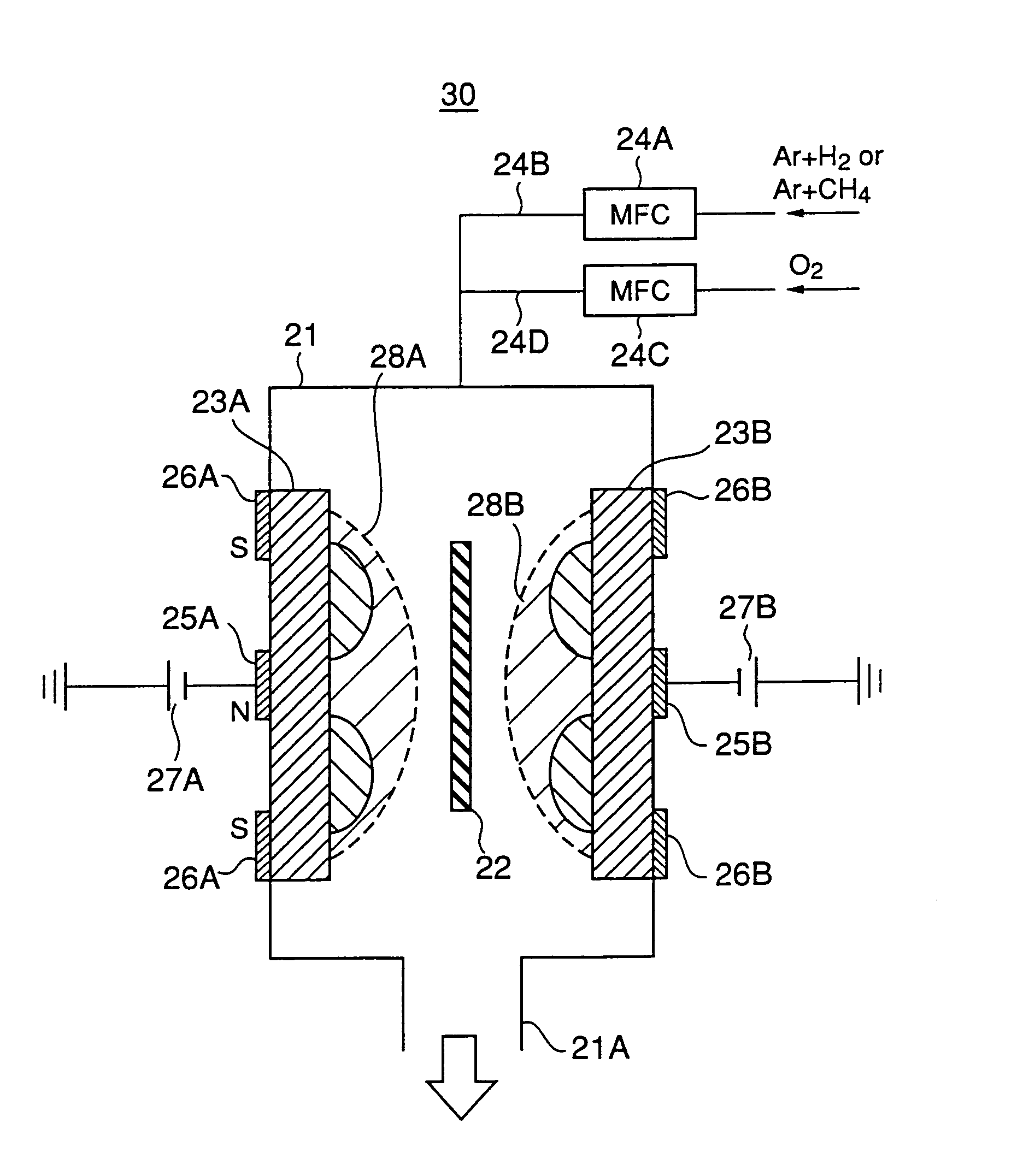
[0113]FIG. 5 shows the construction of a d.c. magnetron sputtering apparatus 30 used for forming a DLC film in a first embodiment of the present invention, wherein those parts corresponding to the parts described previously are designated by the same reference numerals.

[0114]Referring to FIG. 5, the sputtering apparatus 30 has a construction similar to the sputtering apparatus 20 of FIG. 4 except that the sputtering apparatus 30 includes additional mass-flow controller 24C and a line 24D for supplying oxygen into the processing chamber 21.

[0115]Thus, by using the sputtering apparatus 30 of FIG. 5, it becomes possible to carry out a sputtering process in a plasma atmosphere containing oxygen radical, wherein the oxygen radical thus formed in the processing chamber 21 immediately reacts with and removes any DLC film or DLC particles that are formed on the surface of the graphite target 23A or 23B in correspondence to the central region thereof where the plasma density is low.

[0116]Thu...

experiment 2

[0125]FIG. 7B shows the observed arc events per minute for the experiment in which the deposition of the DLC film 31E is conducted on the substrate 22 under a condition similar to the case of the experiment of FIG. 7A, except that an oxygen gas is supplied to the processing chamber 21 from the line 24D with a flow-rate of 1 SCCM in addition to the mixed gas of Ar / CH4 supplied with a flow-rate of 99 SCCM from the line 24B. Thus, in the experiment of FIG. 7B, the sputtering atmosphere contains 1% of oxygen in terms of flow-rate, and a deposition rate of 1.96 nm / second was obtained for the DLC film 31E on the substrate 22.

[0126]Referring to FIG. 7B, it can be seen that occurrence of the arc event is successfully and effectively suppressed as a result of addition of oxygen to the sputtering atmosphere. While a few arc events are recognized after ten hours from the start of the deposition, no appreciable increase of the arc events is observed until 25 hours from the start of the depositi...

experiment 3

[0129]FIG. 7C shows the observed arc events per minute for the experiment in which the deposition of the DLC film 31E is conducted on the substrate 22 under a condition similar to the case of the experiment of FIG. 7A or FIG. 7B, except that an oxygen gas is supplied to the processing chamber 21 from the line 24D with a flow-rate of 10 SCCM in addition to the mixed gas of Ar / CH4 supplied with a flow-rate of 90 SCCM from the line 24B. Thus, in the experiment of FIG. 7C, the sputtering atmosphere contains 10% of oxygen in terms of flow-rate, and a deposition rate of 1.76 nm / second was obtained for the DLC film 31E on the substrate 22.

[0130]Referring to FIG. 7C, it can be seen that occurrence of the arc event is successfully and effectively suppressed as a result of addition of oxygen to the sputtering atmosphere. While a few arc events are recognized after 36 hours from the start of the deposition, no arc event was observed at all until 30 hours from the start of the deposition.

[0131]...


PUM

PropertyMeasurementUnit
half-height widthaaaaaaaaaa
separation distanceaaaaaaaaaa

Abstract

A magnetic disk is produced with improved yield by forming a DLC protective film by a d.c. magnetron sputtering process conducted in a sputtering atmosphere containing oxygen. The magnetic disk carries a lubricating film on the DLC film wherein a fluorocarbon resin constituting the lubricating film contains photocrosslinking groups. A lubricating film having non-polar end groups is also disclosed.

Description

CROSS-REFERENCE TO RELATED APPLICATION[0001]The present application is based on Japanese priority applications No.11-301349, 11-312728 and 11-336458 respectively filed on Oct. 22, 2000, Nov. 2, 2000 and Nov. 26, 2000, the entire contents of which are hereby incorporated by reference.BACKGROUND OF THE INVENTION[0002]The present invention generally relates to magnetic recording of information and more particularly to a magnetic disk apparatus called hard disk drive and a surface coating provided on a magnetic disk used in such a hard disk drive.[0003]Hard disk drives are used extensively in various computers as a large-capacity, high-speed auxiliary storage device.[0004]A typical hard disk drive includes a rigid magnetic disk rotated at a high speed and a magnetic head held on a swing arm so as to scan the recording surface of the magnetic disk, wherein the magnetic head scans the recording surface at a high speed generally in a radial direction of the magnetic disk response to the ro...

Claims


Application Information

Patent Timeline
Patent Type & Authority Patents(United States)
IPC IPC(8): G11B5/65C08F2/46
CPCC23C14/024C23C14/0605G11B5/8408G11B5/725Y10T428/1164G11B5/7257
Inventor WATANABE, KEIJICHIBA, HIROSHIYAMAKAWA, EISHINITANI, TSUKASANAKAMURA, NORIKAZUSUDA, SHOICHITAKEDA, MASAYUKIKURIHARA, KAZUAKI
Owner KK TOSHIBA
Why Eureka
Try Eureka