Percutaneous bypass graft and securing system

Inactive Publication Date: 2006-08-01
CONVERGE MEDICAL
View PDF154 Cites 67 Cited by
  • Summary
  • Abstract
  • Description
  • Claims
  • Application Information

AI Technical Summary

Benefits of technology

[0024]Thus, in accordance with the present invention, bypass grafts are deployed more easily usi

Problems solved by technology

Stenosed vessels cause ischemia which

Method used


Image

  • Percutaneous bypass graft and securing system
  • Percutaneous bypass graft and securing system
  • Percutaneous bypass graft and securing system

Examples


Embodiment Construction

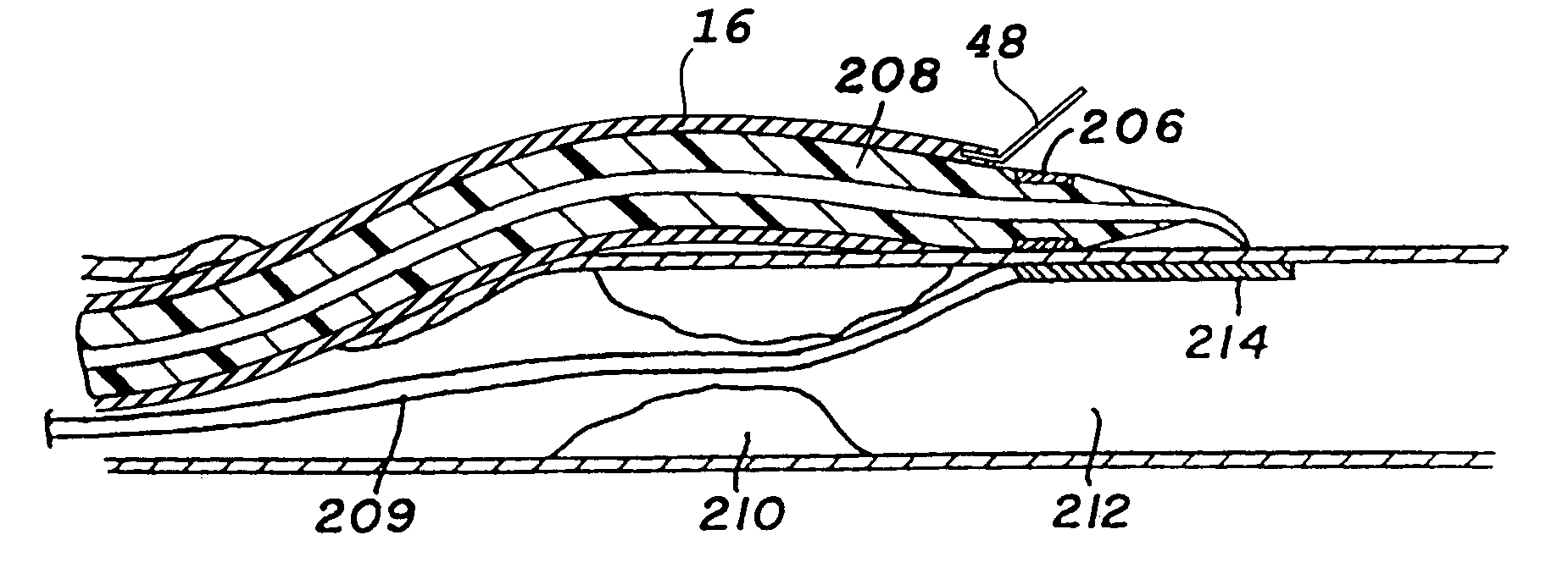
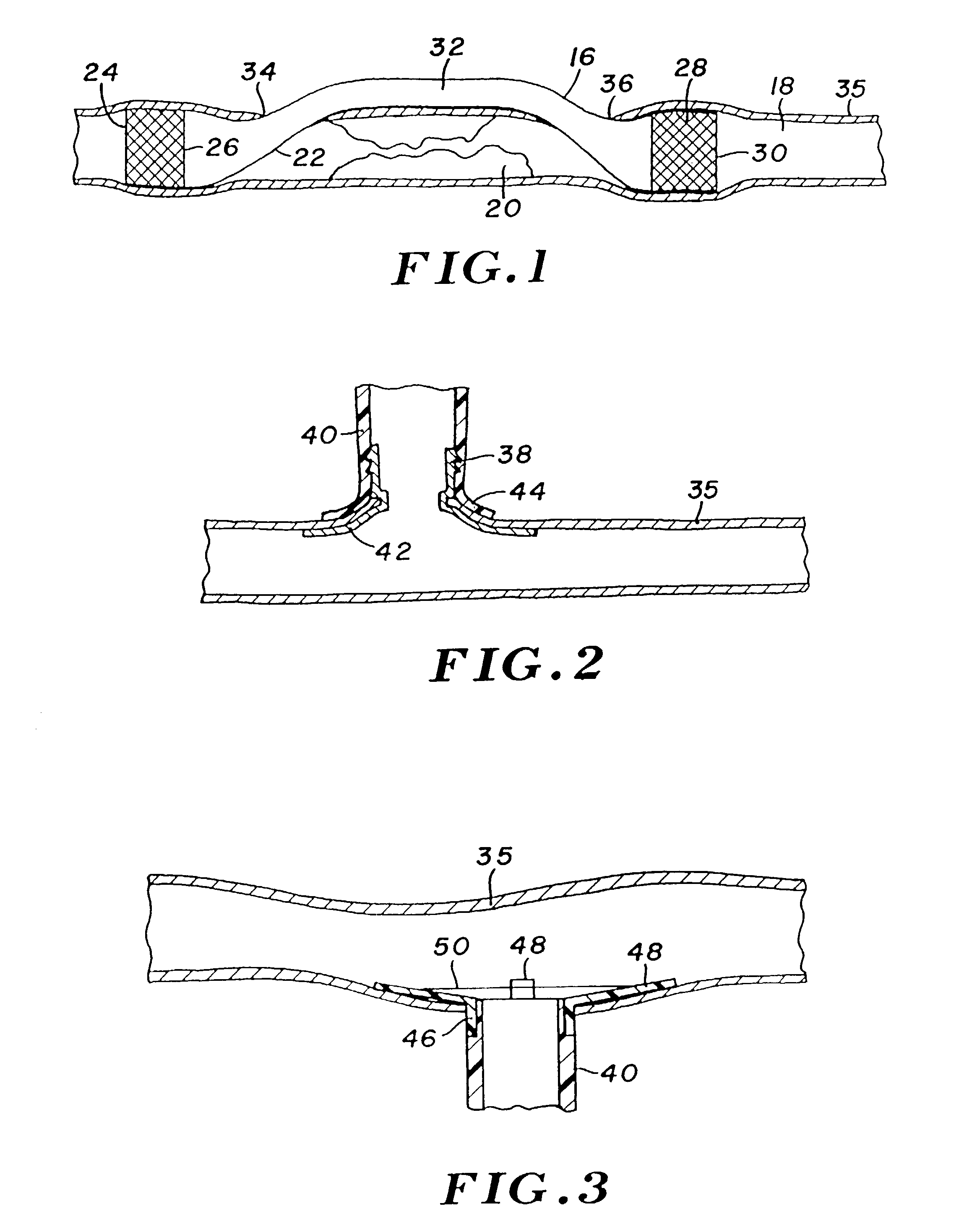
[0042]Turning now to the drawings, there is shown in FIG. 1 a bypass graft 16 secured within a blood vessel 18, in a manner to bypass a lesion 20 within the vessel. Bypass graft 16 has a tubular wall 22 formed of a graft material, e.g., a polymer such as PTFE, urethane, polyimide, nylon, silicone, or polyethylene. The polymer may be extruded, blow molded, or dipped, and formed either directly into a tubing, or formed first as a sheet having opposed ends or edges bonded together to provide the tubular configuration. The edge bond can be formed by a variety of methods including ultrasonic welding, thermal bonding, sewing, adhesives, or with radio frequency (RF) energy. Alternatively, the graft can be a saphenous vein or other vessel from the patient.

[0043]At its proximal end 24, bypass graft 16 incorporates a radially expandable stent 26. The graft incorporates a similar stent 28 at its distal end region 30. Once graft 16 is deployed, the stents are radially expanded using a dilatatio...


PUM


Abstract

A bypass graft incorporates fixation mechanisms at its opposite ends, for securing these ends to different locations along a blood vessel, or alternatively to different locations wherein one of the locations is a different vessel or an organ defining a cavity. Mechanical fixation features such as collets or grommets can be employed, enhanced by delivery of an electrical current sufficient to heat surrounding tissue to form a thermal bond. A graft deployment system includes a tissue dilator and a needle for perforating tissue, mounted coaxially within the dilator. Intralumenal systems further include a catheter for containing the dilator.

Description

CROSS-REFERENCE TO RELATED APPLICATIONS[0001]This application is a continuation of U.S. patent application Ser. No. 09 / 903,219, entitled “Percutaneous Bypass Graft and Securing System”, filed Jul. 10, 2001 now abandoned, which is continuation of U.S. patent application Ser. No. 09 / 415,776, entitled “Percutaneous Bypass Graft and Securing System”, filed Oct. 8, 1999, now U.S. Pat. No. 6,293,955, which is a continuation of U.S. patent application Ser. No. 08 / 966,003, entitled “Percutaneous Bypass Graft and Securing System”, filed Nov. 7, 1997, now U.S. Pat. No. 5,989,276, which claims benefit of U.S. Provisional Application Serial No. 60 / 030,733 entitled “Percutaneous Bypass Graft and Securing System”, filed Nov. 8, 1996.BACKGROUND OF THE INVENTION[0002]The present invention relates to grafts implantable to bypass an obstruction or other undesirable condition within a vessel or other tubular organ, and more particularly to systems for deploying such grafts and fixation elements for se...

Claims


Application Information

Patent Timeline
IPC IPC(8): A61B17/08A61B17/00A61B17/11A61B17/34A61F2/00A61F2/06A61F2/24A61M29/00B60D1/00
CPCA61B17/11A61F2/064A61F2/2424A61B17/34A61B2017/00247A61B2017/00252A61B2017/1107A61B2017/1135A61M29/02A61F2/0009A61F2/0022A61F2/2475A61F2250/0067A61B2018/00392
Inventor HOUSER, RUSSELL A.WHAYNE, JAMES G.FLEISCHMAN, SIDNEY D.
Owner CONVERGE MEDICAL
Why Eureka
Try Eureka