Eureka AIR delivers breakthrough ideas for toughest innovation challenges, trusted by R&D personnel around the world.

Heat accumulating method and device

a heat accumulating method and heat storage technology, applied in indirect heat exchangers, lighting and heating devices, immersion heating arrangements, etc., can solve the problems of insufficient storage of thermal energy at a sufficiently high density, difficult to absorb and store effectively the heat of such a low temperature level, etc., to achieve effective utilization of generated electricity and high density

Inactive Publication Date: 2006-08-01
PANASONIC CORP
View PDF6 Cites 20 Cited by
  • Summary
  • Abstract
  • Description
  • Claims
  • Application Information

AI Technical Summary

Benefits of technology

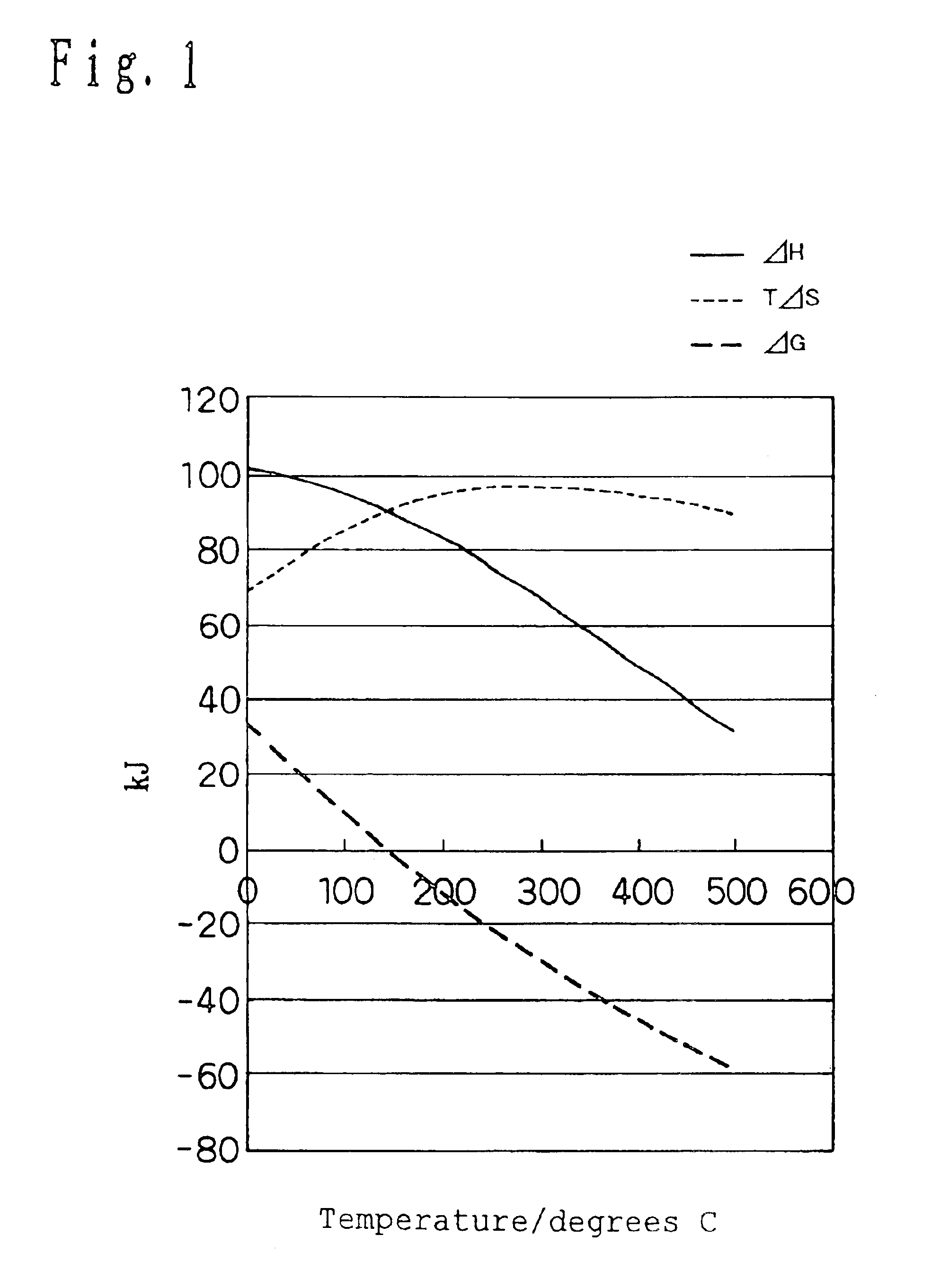
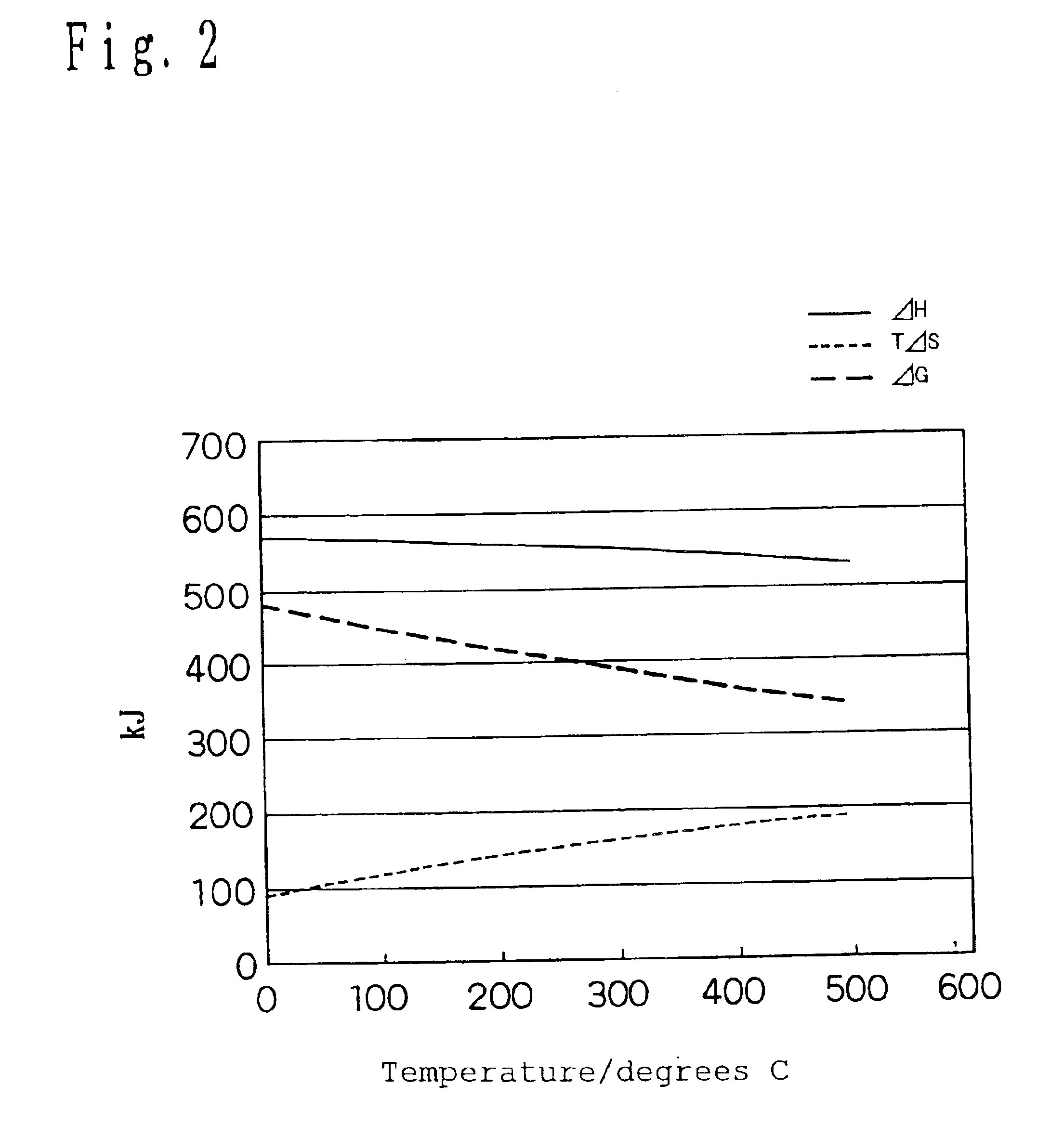
[0082]The thermal storage apparatus according to the present invention is intended to utilize at lower temperature the chemical thermal storage using endothermic and exothermic actions in conjunction with the decomposition of the substance or separation into two or more kinds of composition. And the supplemental energy especially such as electrical energy or light is added as ΔG of the chemical formula 1 shown in FIG. 1 so as to sufficiently promote the decomposition or separation which is thermodynamically difficult at low temperature under normal circumstances and store the energy in total centering on thermal energy.
[0089]And so the one such hydrogen which ion-conducts in the electrolyte by being dissociated and is not poisoning to the electrodes and electrolyte should be selected as the reaction system to be used by the present invention. The reaction system usable from such a viewpoint may be the organic chemical reaction accompanied by a dehydrogenation to hydrogenation reaction, a desorption to dissociation endothermic reaction of the hydrogen by the hydrogen absorbing alloys and so on. From a viewpoint of storability, the substance related to the above reversible reaction system should preferably be condensable or easily storable by physical absorption, chemical absorption and so on.
[0096]According to the present invention, it is possible to generate the electricity by having the exothermic reaction performed via an electrode portion on heat generation reaction. The present invention is characterized by storing the electricity generated here and using it for an electrical or thermal input of the thermal storage reaction portion again or using electric heat conversion means provided separately to convert it to the thermal energy so as to improve thermal storage efficiency including usability by utilizing it together with the thermal storage on heat generation or effectively exploiting it as a heat source for air conditioning and heating. It is also possible to utilize the generated electricity and convert it to cold by using the above electric heat conversion means for instance, it becomes possible to supply the heat in the form of a refrigerator or basic air conditioning to meet a domestic heat demand ratio. It is also feasible to use the heat pump as the electric heat conversion means so as to take out and appropriately use both the heat and cold.
[0098]According to the present invention, it is possible to provide the thermal storage method and thermal storage apparatus by the chemical thermal storage method capable of storing the heat of the domestic hot water supply level at a higher density. It is also possible to provide the thermal storage apparatus, thermal storage method and heat source system capable of generating the electricity on radiation and effectively utilizing the generated electricity.

Problems solved by technology

As for a hot-water storage tank used for an electric water heater and a compression-type heat pump hot-water supply apparatus, installation space thereof is a serious factor in blocking its diffusion in view of housing complexes and urban housing situation so that further miniaturization of a thermal storage tank is demanded.
However, in the case of applying a chemical thermal storage method using a system using an inorganic chemical reaction capable of operating at low temperature of a room temperature level or hydrogen absorbing alloys to a use which needs to efficiently store low-temperature heat of less than 100 degrees C. such as the above hot-water storage tank, it is not possible to store thermal energy at a sufficiently high density.
As for domestic heat storage, however, it is necessary to store heat quantity as low as possible such as less than 70 degrees C., and it is difficult to absorb and store effectively the heat of such a low temperature level by using the chemical reaction exemplified by the above chemical formula 1.

Method used


Image

  • Heat accumulating method and device
  • Heat accumulating method and device
  • Heat accumulating method and device

Examples


first embodiment

(First Embodiment)

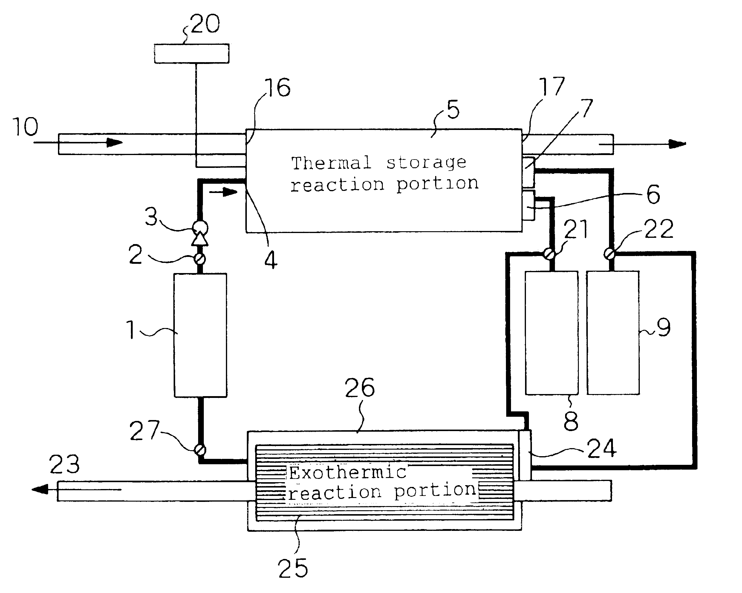
[0191]FIG. 3 shows a block diagram of a thermal storage apparatus according to a first embodiment characterized by supplying electrical energy as supplemental energy by using a thermal rage method of the present invention. A description will given, based on FIG. 3, as to a configuration and an operation the case of utilizing relationships in the formula 3 and the chemical formulas 2 and 3, and a description will be given based on 2-propanol / acetone (1)+hydrogen system (thermal storage density: 745 kJ / kg) of No. 2 in Table 1.

[0192]A valve 2 opens, and the 2-propanol which is the thermal storage material from a thermal storage material tank 1 is supplied by a pump 3 to the inside of a thermal storage reaction portion 5 from a thermal storage material supply port 4. In the thermal storage reaction portion 5, the 2-propanol is decomposed (dehydrogenizing reaction) and converted to acetone and hydrogen by heat of a fluid passage 10 and the electrical energy supplemental...

second embodiment

(Second Embodiment)

[0207]The thermal storage apparatus according to a second embodiment of the present invention will be described as to its configuration and operation based on FIGS. 6 and 7. FIG. 6 shows a schematic view of the thermal storage apparatus according to the second embodiment, and FIG. 7 shows a schematic view of the thermal storage reaction portion thereof. The second embodiment and the first embodiment are different in that the supplemental energy equivalent to ΔG in the thermal storage reaction portion 5 is electricity according to the first embodiment while that is light according to the second embodiment.

[0208]According to the second embodiment, the supplemental energy is light, and so it is constituted as shown in FIG. 7 so that the light from a light exposure portion 28 is effectively illuminated on the catalyst of the thermal storage reaction portion 5. The thermal storage reaction portion 5 is comprised of the light exposure portion 28, the fluid passage 10 an...

third embodiment

(Third Embodiment)

[0218]FIG. 8 shows a block diagram of the thermal storage apparatus according to a third embodiment of the present invention. A description will be given, based on FIG. 8, as to the configuration and operation of the thermal storage apparatus according to the third embodiment utilizing the relationships in the chemical formulas 2 and 3.

[0219]On the thermal storage, the hot water generated by the sunlight, electric heater and heat pump hot-water supply apparatus and so on is circulating in a fluid passage 44. The hot water may be another heat medium such as a cooling medium heated in a refrigeration cycle of a heat pump for instance.

[0220]First, the operation on the thermal storage will be described. A valve 36 opens, and the 2-propanol as the thermal storage material from a thermal storage material tank 35 is supplied by a pump 37 to the inside of a thermal storage reaction portion 39 from a thermal storage material supply port 38. In the thermal storage reaction p...


PUM


Abstract

It is not possible to store heat of a domestic hot water supply level at a high density. If thermal storage temperature is T, variation in enthalpy in a chemical reaction is ΔH, variation in entropy is ΔS, and variation in free energy is ΔG, a thermal storage material satisfying a relationship of TΔS≧ΔG is used under a condition of ΔH>0 so as to promote a reaction for putting the thermal storage material in a thermal storage reaction portion in an energy storing state by having supplemental energy added by an electrode portion when putting the thermal storage material in the energy storing state by decomposing or separating it.

Description

BACKGROUND OF THE INVENTION[0001]1. Field of the Invention[0002]The present invention relates to a thermal storage method and a thermal storage apparatus of which primary object is thermal storage, and a heat source system using those. For instance, it relates to the thermal storage method, thermal storage apparatus and heat source system used for hot-water supply, heaters and heating.[0003]2. Related Art of the Invention[0004]As for the conventional thermal storage apparatuses, for instance, there are the ones utilizing sensible heat of water such as a hot-water storage unit attached to an electric water heater and a compression-type heat pump hot-water supply apparatus, the ones utilizing the sensible heat of a solid such as a brick used for a thermal storage fan heater, and the ones utilizing latent heat utilizing phase change of a substance, and some of them are already put into practical use (for instance, refer to Chemical Industry Council “Thermal Storage Technology—Theory an...

Claims


Application Information

Patent Timeline
Patent Type & Authority Patents(United States)
IPC IPC(8): F24H1/10F28D20/00
CPCF28D20/003F28D20/028Y02E60/145Y02E60/142Y02E60/14
Inventor TERASHIMA, TETSUOSUZUKI, MOTOHIRO
Owner PANASONIC CORP
Why Eureka
Eureka Blog
Learn More