Well testing system

Inactive Publication Date: 2006-08-08
EXPRO NORTH SEA
View PDF9 Cites 6 Cited by
  • Summary
  • Abstract
  • Description
  • Claims
  • Application Information

AI Technical Summary

Benefits of technology

[0009]This is achieved by providing a string with at least two well conduits which may be a concentric or non-concentric parallel configuration. One conduit is used to produce formation fluids to surface or to produce/store unrepresentative initial flow products and the other conduit is used to store formation fluid. The storage conduit can be filled from the top (surface) or the bottom of the well. In a preferred arrangement a valve is provided between the storage conduit and the well annulus for well pressure control, and a shut-in or test valve, which is controllable from surface, is disposed in the non-storage production conduit. A flow control valve is provided at the lower en

Problems solved by technology

Minimising the environmental impact of well testing has, for some time, been a major issue in the oil industry.
Traditional well test operations involves the production and disposal of hydrocarbons creating large quantities of both greenhouse and noxious emissions and the relatively high risk of pollution due to inefficient combustion of the hydrocarbons or accidental spillage.
The amount of information which is obtained by downhole logging systems is limited, primarily due to small volumes which flow from the formation providing samples which can be contaminated by fluids used during the drilling wells and also due to a very small radius of investigation into the reservoir which can lead to the skin effect (formation damage created by the drilling process) having an overwhelming effect on the information obtained.
The close chamber testing minimises the environmental impact of the test but, once again, d

Method used


Image

  • Well testing system
  • Well testing system
  • Well testing system

Examples


Embodiment Construction

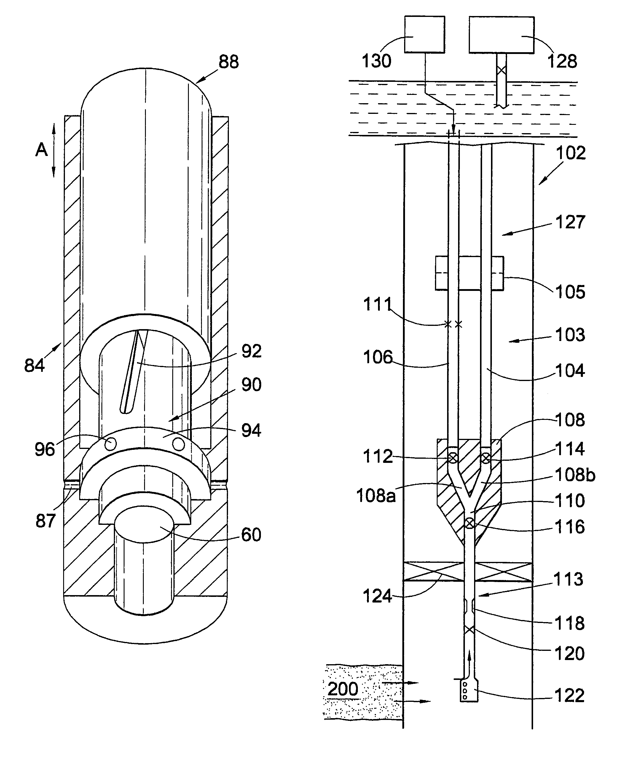
[0058]Reference is first made to FIG. 1 of the drawings which depicts a low environmental impact test string 10 disposed in a subsea well 12 which has a casing 14. The term ‘string’ is used to denote a plurality of tubular elements which are coupled together at surface and fed downhole to create a structure of continuous conduits through which fluid can flow between the surface and the downhole formations. The test string 10 has an inner main bore conduit 16 and a concentric outer conduit 18 defining an annular formation fluid storage volume 19 therebetween. The inner conduit extends to the formation fluid producing zone 20 at sand face 22. A packer 24 seals the main bore conduit 16 to the casing 14 and creates a well annulus 26 between the conduit 18 and casing 14. Disposed in the main bore 16 is a pressure measuring device 28 and a flowmeter 30 for measuring the pressure of formation fluid as will be described.

[0059]A sleeve valve 32 is disposed in conduit 18 and the sleeve valve ...


PUM


Abstract

A well testing system and well testing method is described which can be operated as a closed system with no production of hydrocarbons outside the well or gas can be separated and flared at surface giving minimal environmental impact with the liquid hydrocarbon being re-injected. This is achieved by providing a string with at least two well conduits which may be arranged in a concentric or non-concentric parallel configuration. One conduit is used to produce formation fluids to surface or to produce/store unrepresentative initial flow products and the other conduit is used to store formation fluid. The storage conduit can be filled from the top (surface) or the bottom of the well. In a preferred arrangement a valve is provided between the storage conduit and the well annulus for well pressure control, and a shut-in or test valve, which is controllable from surface, is disposed in the non-storage production conduit. A flow control valve is provided at the lower end of the string or at surface and the size of the valve opening is controllable to allow formation fluid to enter the storage string at a controlled rate, so that the formation fluid flowing time is increased to maximise the radius of investigation into the formation to a similar order of magnitude of existing production tests and extended well tests, which are typically two to three times the order of magnitude of the radius of investigation of a wireline formation test. Other aspects and embodiments of the invention are described.

Description

FIELD OF THE INVENTION[0001]The present invention relates to a well testing system and to a method of conducting a well test. The invention also relates to a flow control valve for use with the well test system.BACKGROUND OF THE INVENTION[0002]Minimising the environmental impact of well testing has, for some time, been a major issue in the oil industry. In some areas of the world, legislation and taxation upon greenhouse gases produced can double the cost of a well test. The ability to conduct a well test without the necessity to flare the produced hydrocarbons and still obtain the quality and quantity of data required to allow formation to be evaluated correctly would significantly increase the number of tests conducted on a worldwide basis.[0003]Traditional well test operations involves the production and disposal of hydrocarbons creating large quantities of both greenhouse and noxious emissions and the relatively high risk of pollution due to inefficient combustion of the hydroca...

Claims


Application Information

Patent Timeline
IPC IPC(8): E21B7/00E21B17/18E21B34/06E21B49/08F16K31/528
CPCE21B17/18E21B49/087E21B34/066
Inventor EDWARDS, JEFFREY CHARLESRICHARDS, ANDREW
Owner EXPRO NORTH SEA
Why Eureka
Try Eureka