Electroconductive contact unit

a contact unit and electroconductor technology, applied in the direction of superimposed coating process, coupling device connection, instruments, etc., can solve the problems of inability to regain original electric property, inability to meet the electric properties of existing needle members made of noble metal alloys, and inability to meet the electric properties of existing needle members. to achieve the effect of high hardness and wear resistance, high durability, and high electroconductivity of the electric path between the needle member and the coil spring

Inactive Publication Date: 2006-08-15
NHK SPRING CO LTD
View PDF12 Cites 7 Cited by
  • Summary
  • Abstract
  • Description
  • Claims
  • Application Information

AI Technical Summary

Benefits of technology

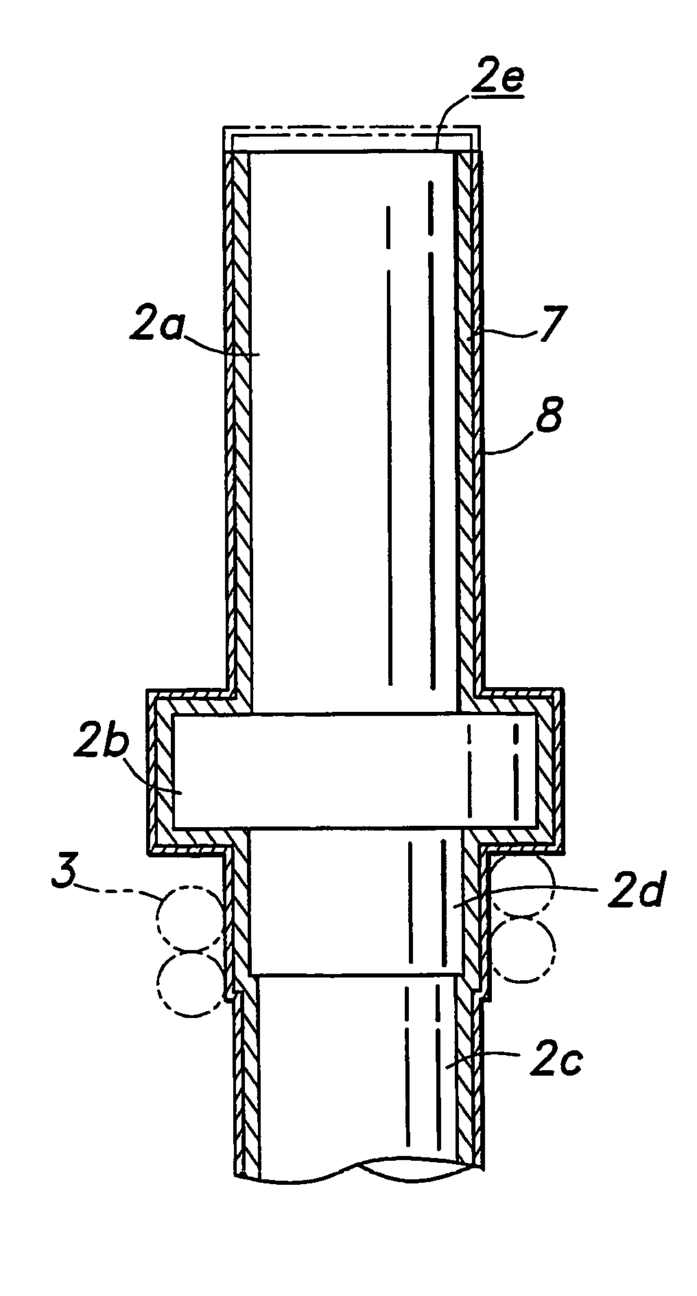
[0009]Thus, because the needle member is made of the noble metal alloy having a high hardness and wear resistance, it is highly durable in the sense that it can withstand numerous contacts. Owing to the fact that the outer circumferential surface of the needle member is plated with gold, the electroconductivity of the electric path between the needle member and coil spring can be maximized. In particular, because the contact surface is defined by exposing the noble metal alloy by grinding, even when the contact surface is soiled by solder after repeated contacts with such contact objects as solder balls, the contact surface can be renewed simply by grinding the contact surface, and the renewed surface consists of the exposed surface of the noble metal alloy which is not different from the original contact surface. Therefore, the contact resistance between the contact surface and object of contact would remain unchanged even by the repeated renewing of the contact surface.
[0010]If the noble metal alloy contains palladium and at least two members selected from a group consisting of silver, platinum, gold, copper and zinc, the needle member can be made highly hard and wear resistant. In particular, if the noble metal alloy contains at least palladium, silver and copper, the needle member can be made not only highly hard and wear resistant but also favorably electroconductive. If the plating material having a high electroconductivity consists of gold, a high resistance to corrosion and favorable electric properties can be ensured in a stable manner.
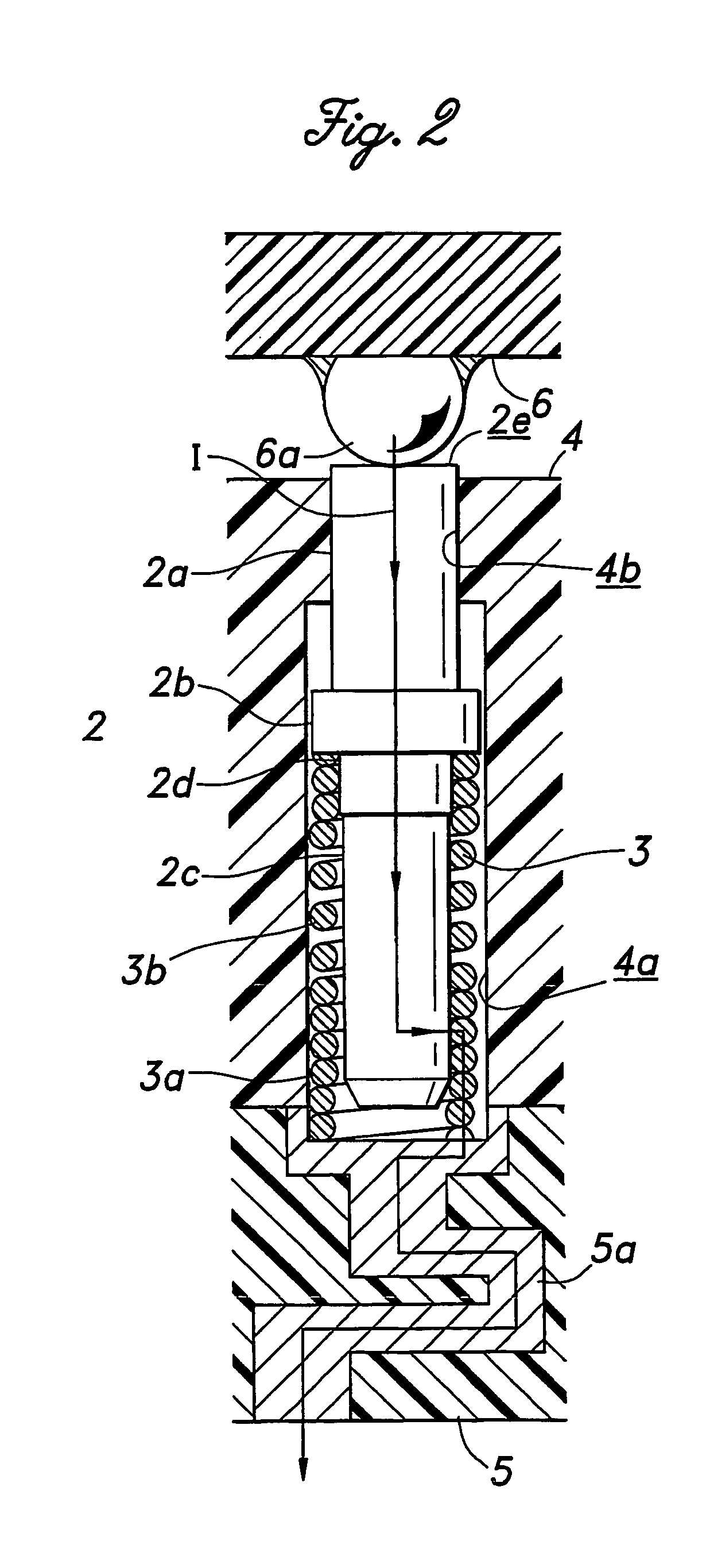
[0011]If the electroconductive contact unit further comprises a second electroconductive needle member at the other end of the coil spring, and the coil spring comprises a closely wound portion interposed between the first needle member and second needle member, even when one of the electroconductive needle members is made of a noble metal alloy having a high hardness and wear resistance but too poor in workability to allow the diameter of the needle member to be reduced to a desired level, owing to the presence of the closely wound portion in the coil spring between the two needle members, as can be readily appreciated, the electric signal can flow axially through the closely wound portion of the compression coil spring, instead of along a spiral path, so that the inductance of the electroconductive contact unit can be effectively minimized. Therefore, even when the length of one of the needle members cannot be adequately increased, and the distance between the two needle members is thereby made relatively large, the inductance of the electric path between the two needle members can still be minimized.

Problems solved by technology

When a needle member is applied repeatedly to solder balls, solder inevitably deposits on the contact surface of the needle member over time.
On the other hand, when the needle member is made of SK material (carbon tool steel) and is provided with a plated surface, grinding of the contact surface only exposes the material of the needle member, and the original electric property cannot be regained.
As the performance of the semiconductor products becomes higher, the electric properties of the existing needle member made of a noble metal alloy are found to be more and more unsatisfactory.
However, increasing the thickness of the gold plated layer increases the manufacturing cost of the needle member, and the needle member cannot be ground not so many times as desired.

Method used


Image

  • Electroconductive contact unit
  • Electroconductive contact unit
  • Electroconductive contact unit

Examples


Embodiment Construction

[0019]Preferred embodiments of the present invention are described in the following with reference to the appended drawings.

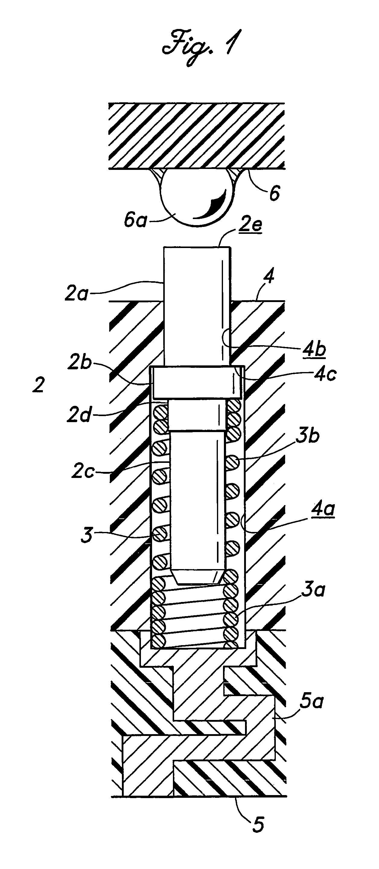
[0020]FIG. 1 is a vertical sectional view showing an electroconductive contact unit 1 for use in a contact probe embodying the present invention. This electroconductive contact unit 1 may be used by itself, but is particularly suitable for use in a holder (probe head) of a multipoint contact probe as one of a large number of similar electroconductive contact units that are arranged one next to another, for instance for a wafer level test. In such a contact probe, the holder is integrally attached to a board mounted on a testing machine via a relay circuit board. The drawing is for illustration purpose only, and the actual aspect ratio may differ from that of the illustrated example.

[0021]The electroconductive contact unit 1 comprises an electroconductive needle member 2, a compression coil spring 3 and a holder 4 made of electrically insulating material and def...


PUM

PropertyMeasurementUnit
hardnessaaaaaaaaaa
wear resistanceaaaaaaaaaa
electroconductiveaaaaaaaaaa

Abstract

In the electroconductive contact unit of the present invention, an electroconductive needle member 2 is made of a noble metal alloy having a high hardness and wear resistance, and formed with a gold plated layer 8 via a Ni under layer 7, and a flat surface 2e is formed by a tip portion thereof so as to expose the material of the needle member. Thereby, the durability of the needle member is ensured and the electroconductivity of the electric path between the needle member and coil spring is minimized on account of the gold plated layer. Even when the contact surface is soiled by solder deposition after repeated applications to contact objects such as solder balls, simply grinding the contact surface and revealing a new surface, the contact resistance between the contact surface and contact object can be kept unchanged by grinding so that the test can be conducted with the benefit of low resistance at all times.

Description

CROSS REFERENCE TO RELATED APPLICATIONS[0001]This present application is a 35 USC 371 national stage application of PCT / JP02 / 06648, filed Jul. 1, 2002, which in turn claims priority from prior Japanese application 2001-201176, filed Jul. 2, 2001.TECHNICAL FIELD[0002]The present invention relates to an electroconductive contact unit for exchanging signals with printed circuit boards, electronic devices or the likes.BACKGROUND OF THE INVENTION[0003]A conventional electroconductive contact unit for use in contact probes for electrically testing conductor patterns of printed circuit boards and electronic devices typically comprises an electroconductive needle member and a tubular holder that receives the needle member in an axially moveable manner, and the needle member is resiliently urged by a coil spring in the direction to project the tip of the needle member from the front end of the holder so that the tip of the needle member may be resiliently brought into contact with an object ...

Claims


Application Information

Patent Timeline
Patent Type & Authority Patents(United States)
IPC IPC(8): G01R31/02G01R31/00G01R31/26C22C5/00C23C28/00C23C28/02G01R1/067H01H1/023H01R13/03H01R13/24
CPCC23C28/023H01R13/03G01R1/06722H01R13/2421H01R2201/20H01R13/24
Inventor KAZAMA, TOSHIO
Owner NHK SPRING CO LTD
Why Eureka
Try Eureka