
Amplifier and radio frequency power amplifier using the same

a radio frequency power amplifier and amplifier technology, applied in the field of radio frequency power amplifiers, can solve the problems of envelope amplifier b>103/b>, which is not large in bandwidth and highly efficient, and gives rise to clipping distortion at high signal peaks, etc., to achieve low distortion amplifiers, wide band, and high efficiency.

Inactive Publication Date: 2006-09-05
RENESAS ELECTRONICS CORP
View PDF3 Cites 15 Cited by
  • Summary
  • Abstract
  • Description
  • Claims
  • Application Information

AI Technical Summary

Benefits of technology

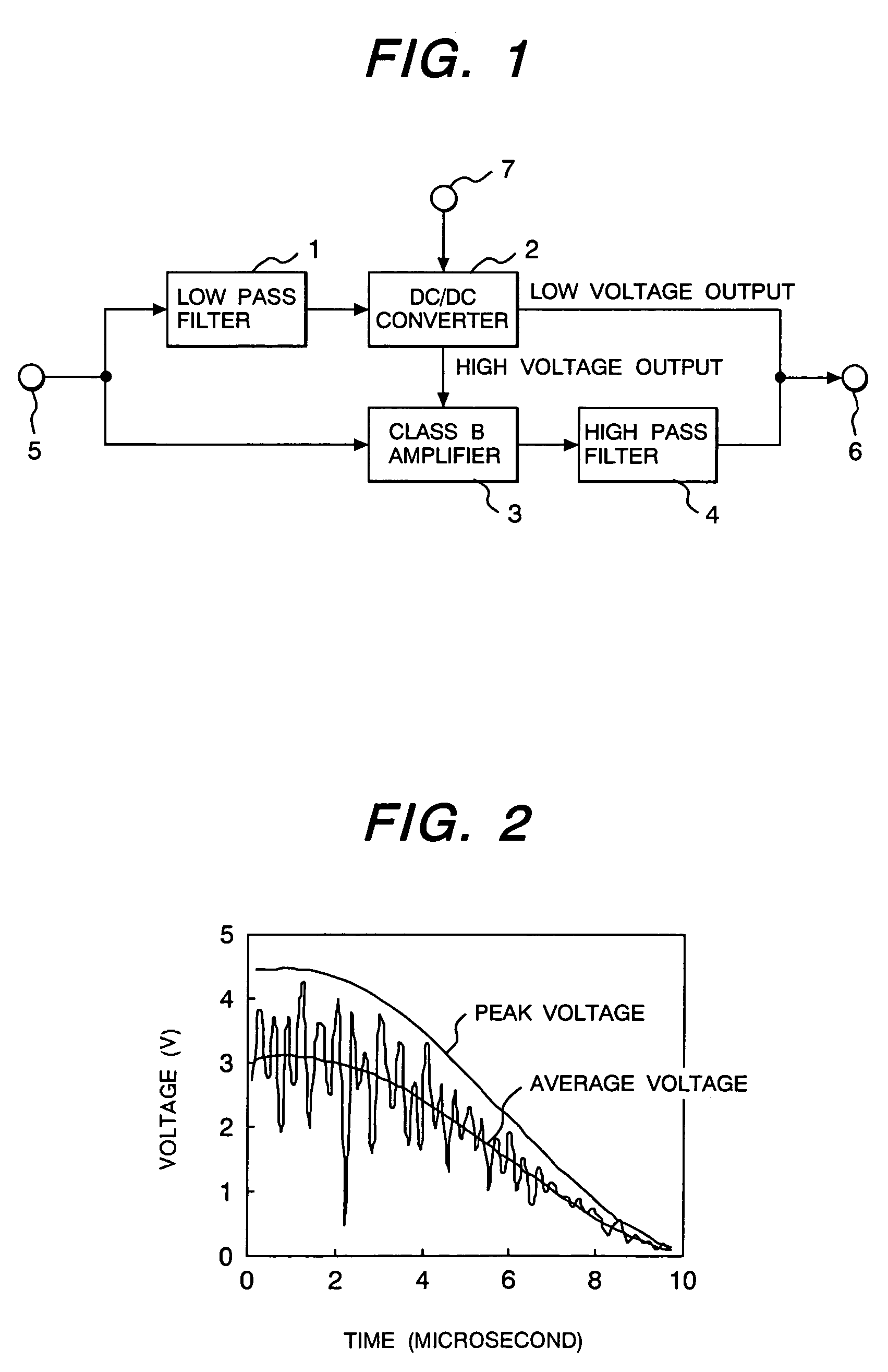
[0015]FIG. 13 shows an envelope signal of W-CDMA, and FIG. 14, its high frequency components. Whereas the high frequency components have peaks at sub-microsecond intervals, the peak levels irregularly fluctuate. In such a case, in order for the power supply circuit according to the prior art to operate normally, the regulator 33 should respond in a short period of time in the sub-microsecond order.
[0018]An object of the present invention is to realize a wide band, high efficiency and low distortion amplifier free from clipping distortion, and a high efficiency and low distortion radio frequency power amplifier applicable to wide band wireless communication systems using the same.

Problems solved by technology

The above-described envelope amplifier 103, though large in bandwidth and highly efficient, is still insufficient for amplifying the envelope signals of W-CDMA having a wide frequency band.
Since the output voltage of the class B amplifier cannot surpass the power supply voltage in actual circuit operation, the envelope amplifier 103 gives rise to clipping distortion at high signal peaks.

Method used


Image

  • Amplifier and radio frequency power amplifier using the same
  • Amplifier and radio frequency power amplifier using the same
  • Amplifier and radio frequency power amplifier using the same

Examples


Embodiment Construction

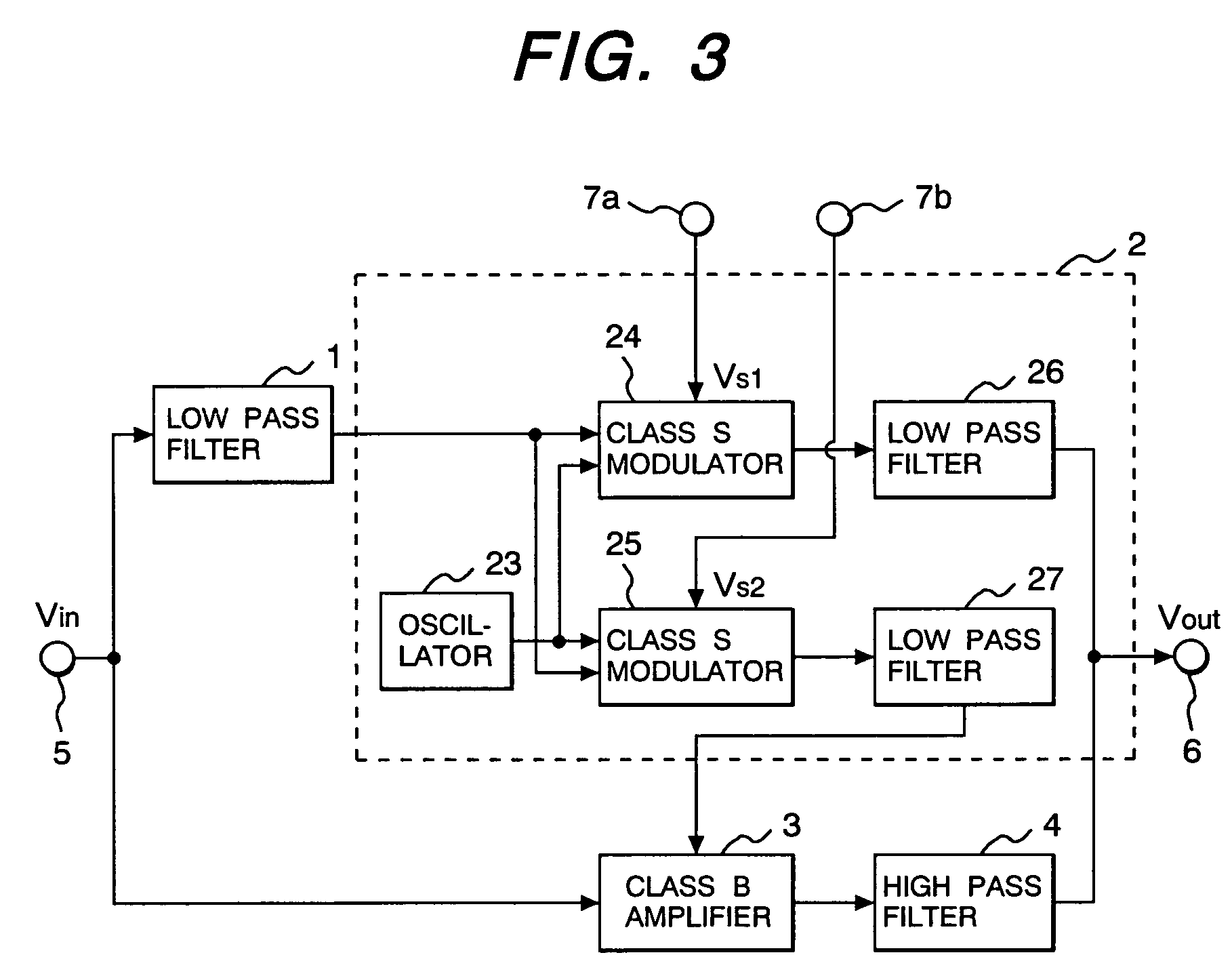
[0037]An amplifier pertaining to the present invention and a radio frequency power amplifier using the same will be described in further detail below with reference to a number of preferred embodiments of the invention illustrated in accompanying drawings. The same reference signs in FIG. 1, FIG. 3 through FIG. 5 and FIG. 7 through FIG. 10 denote respectively the same or like elements.

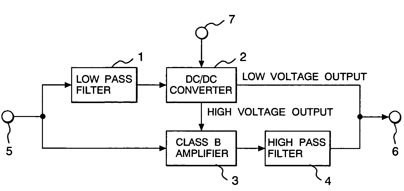
[0038]The amplifier, which is the first preferred embodiment of the invention, is shown in FIG. 1. In FIG. 1, reference numeral 1 denotes a low pass filter for removing the high frequency components, namely the envelope, of an input signal inputted into an input terminal 5; 2, a DC—DC converter for amplifying the output signal of the low pass filter 1; 3; a class B amplifier for amplifying the envelope from the input terminal 5; and 4, a high pass filter for removing the low frequency components of the class B amplifier 3. The DC—DC converter 2 has two output terminals, of which one is connected to the...


PUM


Abstract

An amplifier using a wide band, high efficiency, and low distortion amplifier free from clipping distortion, and a high efficiency and low distortion radio frequency power amplifier, using that amplifier, which can be applied to wide band wireless communication systems are provided. The amplifier has a DC—DC converter 2, augmented with a low pass filter 4, for amplifying the low frequency components of an input signal from a terminal 5, and a class B amplifier, augmented with a high pass filter, for amplifying the input signal and supplying its high frequency components after amplification. The DC—DC converter and the class B amplifier are connected in parallel, and the power supply voltage of the class B amplifier is controlled with the low frequency components of the input signal.

Description

CLAIM OF PRIORITY[0001]The present application claims priority from Japanese applications JP 2003-305657 filed on Aug. 29, 2003 and JP 2004-184669 filed on Jun. 23, 2004, the contents of which are hereby incorporated by reference into this application.FIELD OF THE INVENTION[0002]The present invention relates to a radio frequency power amplifier, and more particularly to a radio frequency power amplifier that can be suitably applied to the transmitter unit of a radio apparatus, such as a cellular phone.BACKGROUND OF THE INVENTION[0003]Cellular phones have come into rapidly expanding use in recent years, resulting in a dramatic increase in the quantity of data communicated. For this reason, high capacity communication systems, such as the wideband code division multiple access (W-CDMA) system, are increasingly introduced for use.[0004]A radio frequency power amplifier for use in the transmitter unit of a cellular phone terminal consumes more power than most other constituent elements ...

Claims


Application Information

Patent Timeline
Patent Type & Authority Patents(United States)
IPC IPC(8): H03F3/38H03G3/20H03F1/02H03F3/20H03F1/32H03F3/19H04B1/04
CPCH03F1/0227H03F2200/432
Inventor MATSUMOTO, HIDETOSHITANOUE, TOMONORIOHNISHI, MASAMI
Owner RENESAS ELECTRONICS CORP
Learn More