
Optical band scanning monitor system and method

a monitor system and optical band technology, applied in the direction of transmission monitoring, optical radiation measurement, instruments, etc., can solve the problems of large number of potential channels on the link, major engineering challenges in the design of add/drop devices,

Inactive Publication Date: 2006-09-05
AXSUN TECH
View PDF16 Cites 3 Cited by
  • Summary
  • Abstract
  • Description
  • Claims
  • Application Information

AI Technical Summary

Benefits of technology

[0005]The present invention is directed to a scanning optical monitoring system and method. Specifically, a system and method are appropriate for high speed scanning of a WDM signal band. The system and method are able to quickly identify dropped channel signals or, more generally, discrepancies between the determined or detected channel inventory and a perpetual inventory for the WDM signal, which perpetual inventory specifies the channel signals that should be present in the WDM signal assuming proper operation of the network.
[0009]In a current implementation, a low pass filter is used to filter the electronic signal from the photodetector prior to reception by the decision circuit. This removes any high frequency interference, allowing the controller to determine the existence, or not, of specific channels during the scan.
[0010]The controller determines the channel inventory by comparing an instantaneous power in the pass band of the tunable filter, typically during the scan, to a threshold of the decision circuit to determine whether or not a channel exists at the current pass band or channel slot. An inventory determined from the scan by the controller is then compared to perpetual inventory information that can be accessed by the controller. In this way, the controller can identify whether or not the WDM signal contains the expected channels.
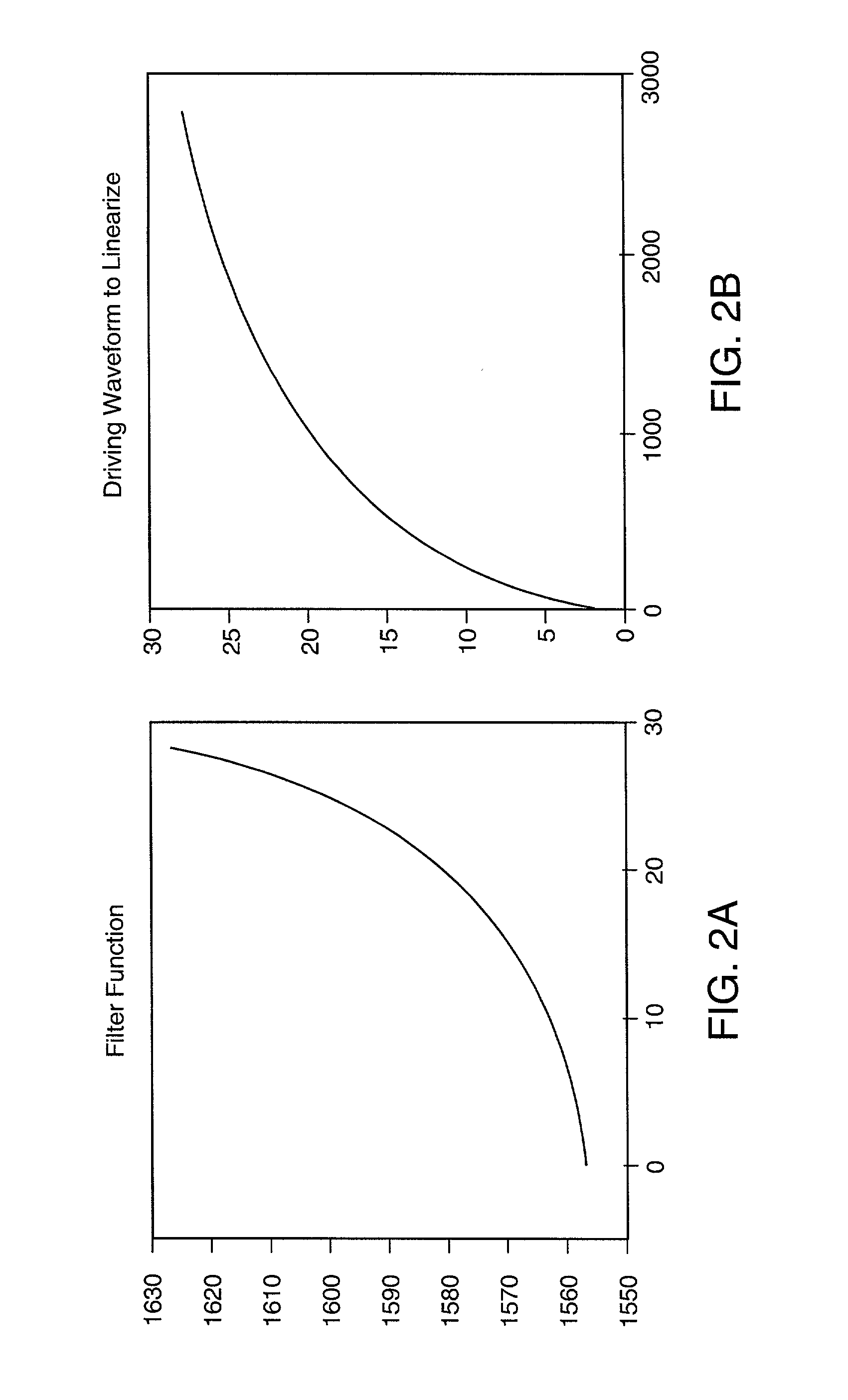
[0013]According to a further embodiment of the invention, a filter tuning voltage generator generates a tuning voltage to the optical tunable filter that improves the linearity of the tuning of the pass band as a function of time over at least a portion of the scan of the signal band. Specifically, in one implementation, the tuning generator is triggered by the controller to in effect generate an arbitrary waveform. The waveform, however, is selected so that the pass band center wavelength changes linearly with time over as least a portion of the scan. Such filter tuning voltage generators map an inverse of a wavelength tuning function of the optical tunable filter. For example, in one implementation, the generator is a look-up table. Alternatively, the filter tuning voltage generators map an inverse of a frequency tuning function of the optical tunable filter. For example, in one implementation, the generator is a look-up table.

Problems solved by technology

Major engineering challenges exist today in the design of add / drop devices that have robust operation.
One such challenge concerns the monitoring of the operation of such devices by reference to the channel signals populating the input and output optical links to the devices.
Further, the number of potential channels on a link can be large.

Method used


Image

  • Optical band scanning monitor system and method
  • Optical band scanning monitor system and method
  • Optical band scanning monitor system and method

Examples


Embodiment Construction

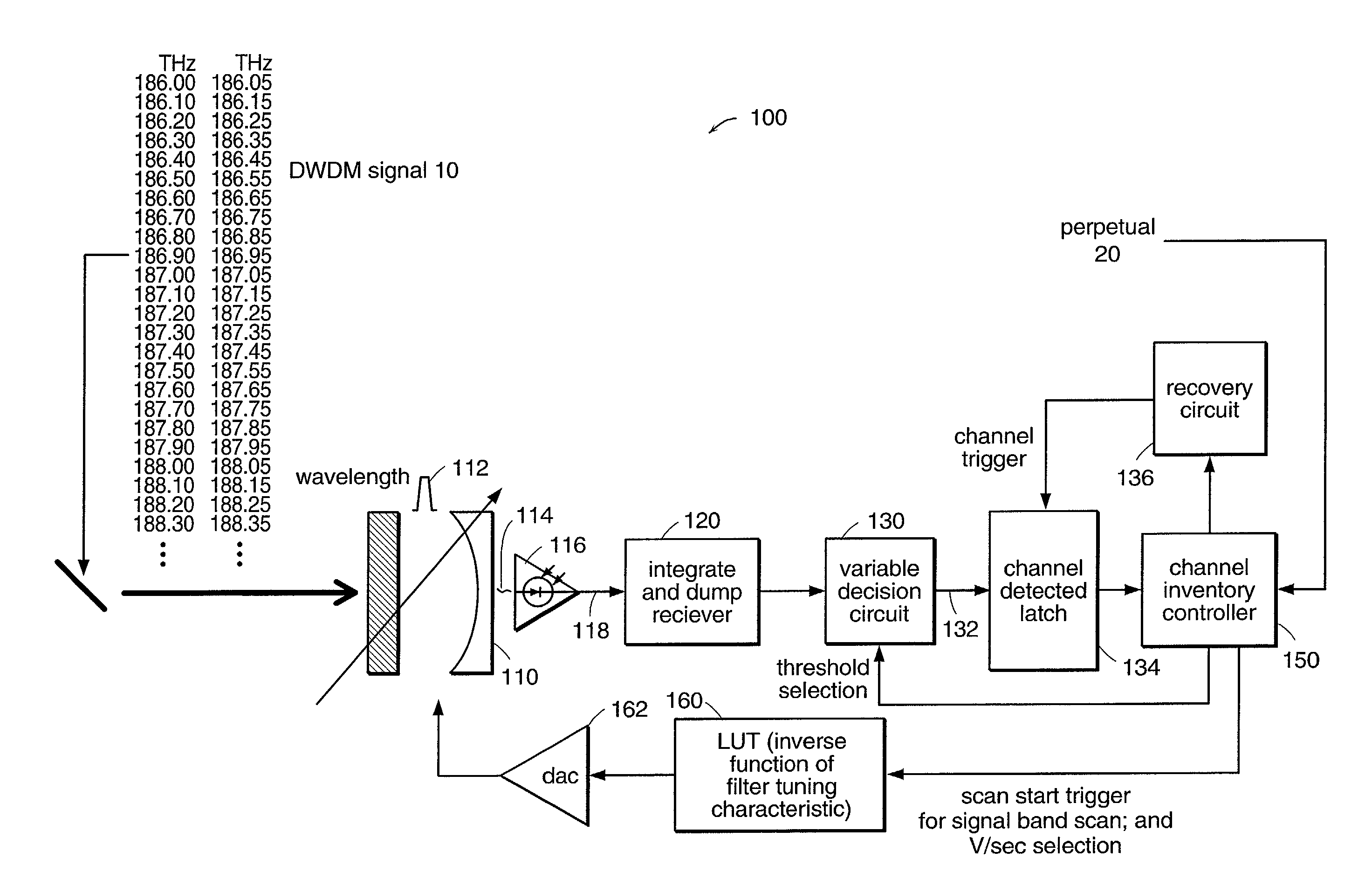
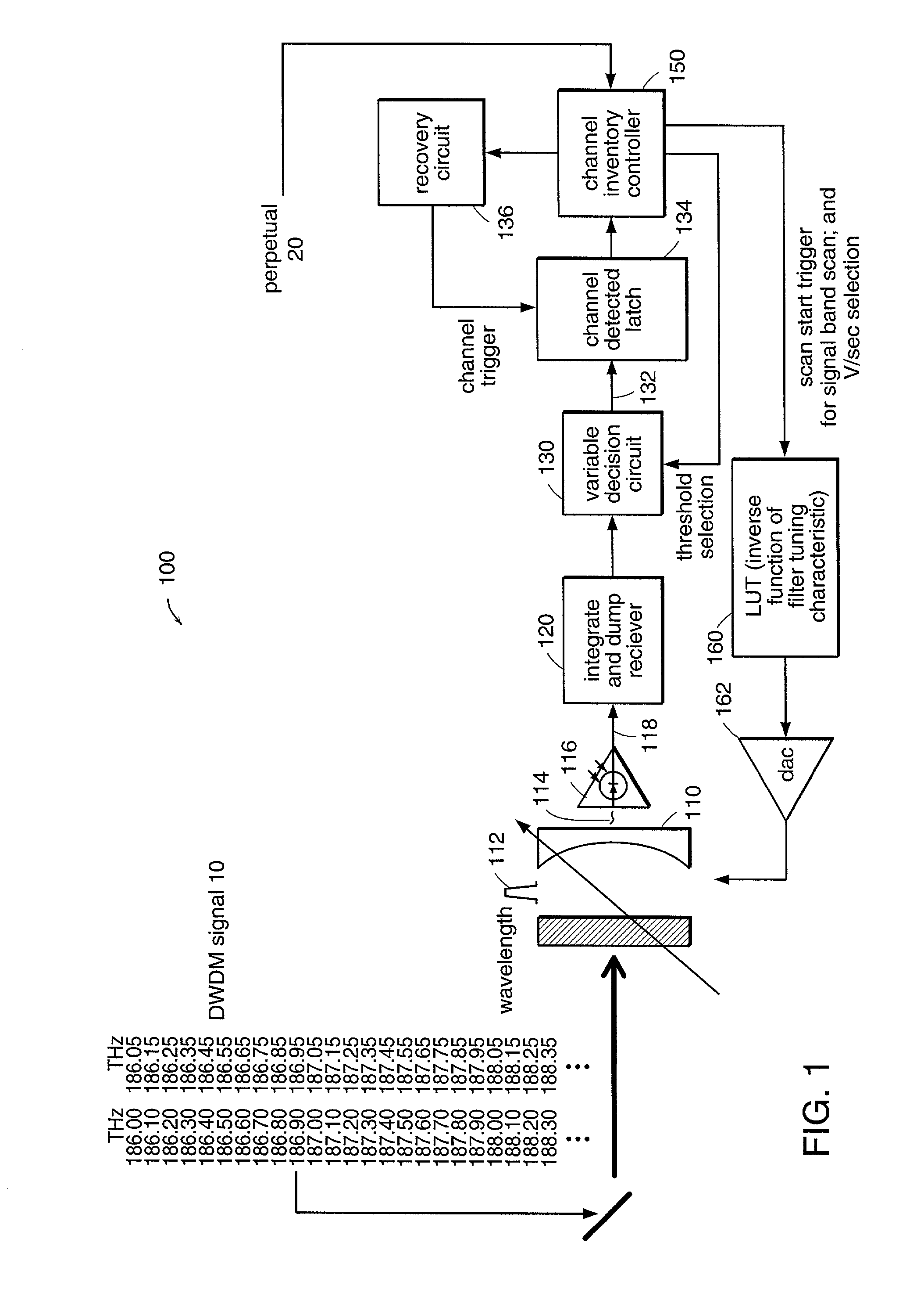
[0021]FIG. 1 is a schematic block diagram illustrating an optical band scanning monitoring system 100, which has been constructed according to the principles of the present invention.

[0022]Specifically, a WDM signal 10 is received by a tunable optical filter 110. In preferred embodiment, this filter is an electrostatically deflected Fabry-Perot device and is preferably a high finesse device that has a tunable pass band that is narrow to resolve the individual channels in the WDM signal. In one implementation, the WDM signal is a DWDM signal that has multiple channel slots across a signal band of the WDM system. In the illustration of FIG. 1, the WDM signal has 100 GHz channel spacings according to the ITU grid or 50 GHz spacing according to the 50 GHz offset. Specifically, in such an implementation, the pass band of the tunable filter 110 is less than 25 GHz, and preferably less then 5 GHz.

[0023]In one embodiment, the free spectral range of the filter 110 is greater than the signal ...


PUM


Abstract

A scanning optical monitoring system and method are appropriate for high speed scanning of a WDM signal band. The system and method are able to identify dropped channels or, more generally, discrepancies between the determined or detected channel inventory and a perpetual inventory for the WDM signal, which perpetual inventory specifies the channels that should be present in the WDM signal assuming proper operation of the network. The system includes a tunable optical filter that scans a pass band across a signal band of a WDM signal to generate a filtered signal. A photodetector then generates an electrical signal in response to this filtered signal. A decision circuit compares the electrical signal to a threshold and a controller, which is responsive to the decision circuit, inventories the channels in the WDM signal.

Description

BACKGROUND OF THE INVENTION[0001]Wavelength division multiplexing (WDM) systems typically comprise multiple separately modulated laser diodes at the transmitter. These laser diodes are tuned to operate at different wavelengths. When combined in an optical fiber, the WDM optical signal comprises a corresponding number of spectrally separated channels. Along the transmission link, the channels are typically collectively amplified in gain fiber, such as erbium-doped fiber and / or regular fiber, in a Raman pumping scheme. At the receiving end, the channels are usually separated from each other using thin film filter systems, to thereby enable detection by separate photodiodes.[0002]The advantage of WDM systems is that the transmission capacity of a single fiber can be increased. Historically, only a single channel was transmitted in each optical fiber. In contrast, modern WDM systems contemplate hundreds or thousands of spectrally separated channels per fiber. Such configurations yield c...

Claims


Application Information

Patent Timeline
Patent Type & Authority Patents(United States)
IPC IPC(8): H04B10/08
CPCH04B10/0795H04J14/0246H04J14/0227H04B10/07957
Inventor KORN, JEFFREY A.ATIA, WALID A.
Owner AXSUN TECH
Learn More